A clamping mechanism for auto parts welding

A technology for auto parts and clamping mechanisms, applied in welding equipment, auxiliary welding equipment, welding/cutting auxiliary equipment, etc., can solve problems such as poor welding, and achieve the effects of precise welding, convenient adjustment and convenient operation.

Active Publication Date: 2019-11-29
重庆友拓汽车零部件有限公司
View PDF6 Cites 0 Cited by
  • Summary
  • Abstract
  • Description
  • Claims
  • Application Information

AI Technical Summary

Problems solved by technology

When welding, it is necessary to fix the workpiece to be welded first, and then use the welding torch for welding. The existing technology mainly relies on manually grasping the workpiece to be welded, but the shaking will inevitably occur when manually grasping the workpiece to be welded, which will lead to welding Bad, so we propose a clamping mechanism for auto parts welding

Method used


Image

  • A clamping mechanism for auto parts welding
  • A clamping mechanism for auto parts welding
  • A clamping mechanism for auto parts welding

Examples


Embodiment Construction

[0017] The following will clearly and completely describe the technical solutions in the embodiments of the present invention with reference to the accompanying drawings in the embodiments of the present invention. Obviously, the described embodiments are only some, not all, embodiments of the present invention.

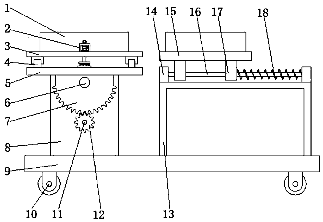
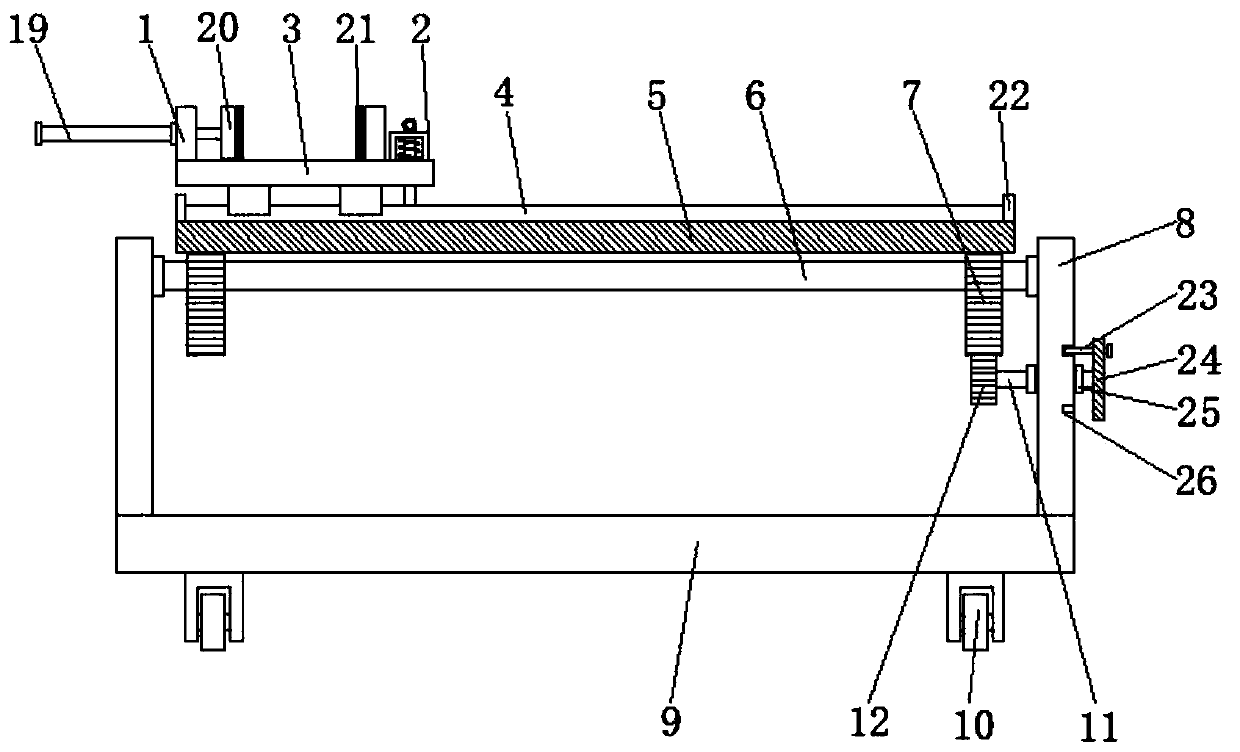
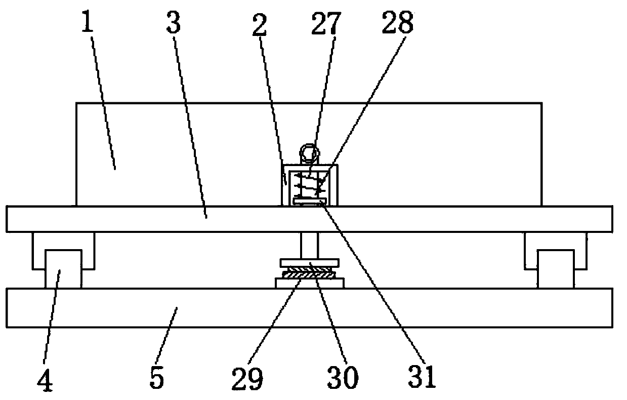
[0018] refer to Figure 1-3 , a clamping mechanism for auto parts welding, comprising a base plate 9, a support plate 8 is arranged symmetrically above the base plate 9, a first rotating shaft 6 is arranged between the supporting plates 8, and the two ends of the first rotating shaft 6 are respectively connected to the supporting plate 8 are movably connected, the first rotating shaft 6 is symmetrically provided with semicircular gears 7, and the semicircular gears 7 are coaxially arranged with the first rotating shaft 6, the top of the semicircular gears 7 is provided with a mounting plate 5, and the bottom of the bottom plate 9 is equidistantly provided with multipl...


PUM


Abstract

The invention relates to the technical field of clamping fixtures, in particular to a clamping mechanism for welding automobile parts. The clamping mechanism comprises a base plate. Supporting platesare symmetrically arranged at the upper side of the base plate. A first rotating shaft is arranged between the supporting plates. The two ends of the first rotating shaft are movably connected with the supporting plates correspondingly. Semicircular gears are symmetrically arranged on the first rotating shaft. A mounting plate is arranged above the semicircular gears. A moving plate is arranged above the mounting plate through a moving mechanism. A second rotating shaft is arranged at one side of one of the supporting plates. One end of the second rotating shaft penetrates through the corresponding supporting plate and is further provided with a gear. The gear is engaged with the corresponding semicircular gear. A fixing mechanism is arranged on the second rotating shaft. A supporting frame is arranged above the base plate and located at one sides of the supporting plates. An electric telescopic rod is arranged at one sides of fixing plates, and an output shaft of the electric telescopic rod penetrates through the fixing plates and is further provided with clamping plates. The clamping plates are located between the fixing plates. The clamping mechanism for welding the automobile parts is convenient to operate and accurate in welding; and meanwhile, the angle of a material can be adjusted conveniently and welding by workers is facilitated.

Description

technical field [0001] The invention relates to the technical field of clamping tooling, in particular to a clamping mechanism for auto parts welding. Background technique [0002] In the process of production and manufacturing, it is often necessary to manufacture larger products, and it is often difficult to form larger products at one time. After the manufacturing is completed, multiple small workpieces are welded together to form larger products. When welding, it is necessary to fix the workpiece to be welded first, and then use the welding torch for welding. The existing technology mainly relies on manually grasping the workpiece to be welded, but the shaking will inevitably occur when manually grasping the workpiece to be welded, which will lead to welding Therefore, we propose a clamping mechanism for auto parts welding. Contents of the invention [0003] The purpose of the present invention is to solve the shortcomings in the prior art, and propose a clamping mec...

Claims


Application Information

Patent Timeline
Patent Type & Authority Patents(China)
IPC IPC(8): B23K37/04
CPCB23K37/0435
Inventor 李占良
Owner 重庆友拓汽车零部件有限公司
Why Eureka
Try Eureka