Terminal device and radio base station device
A technology of radio base stations and terminal devices, which is applied in wireless communication, transmission path separation devices, electrical components, etc., and can solve problems such as increased resources and limited wireless resources
- Summary
- Abstract
- Description
- Claims
- Application Information
AI Technical Summary
Problems solved by technology
Method used
Image

Examples
no. 1 approach
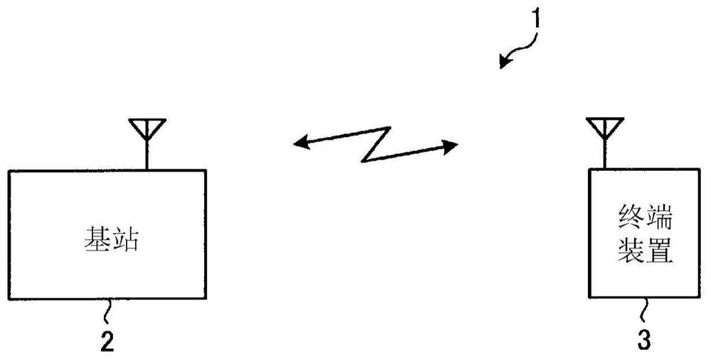
[0055] figure 1 It is an explanatory diagram showing an example of the wireless communication system 1 of the first embodiment. figure 1 The illustrated wireless communication system 1 includes a base station 2 and a terminal device 3 . For example, the base station 2 transmits and receives data (such as eMBB data and URLLC data) to and from the terminal device 3 through a wireless carrier. For example, the base station 2 is a gNB such as an NR cell. For example, the terminal device 3 transmits and receives data (eg, eMBB data and URLLC data) to and from the base station 2 through the wireless carrier.
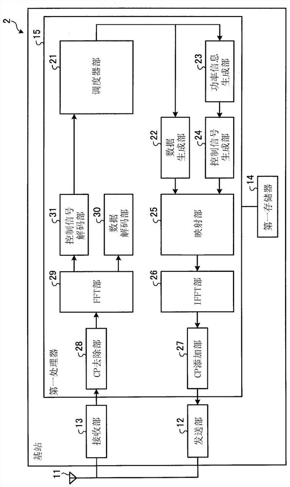
[0056] figure 2 is a block diagram showing an example of the base station 2 of the first embodiment. figure 2 The illustrated base station 2 includes an antenna 11 , a transmitting part 12 , a receiving part 13 , a first memory 14 and a first processor 15 . For example, the antenna 11 transmits and receives wireless signals of a wireless carrier. The transmitter 12 is ...
no. 2 approach
[0092] Image 6 It is an explanatory diagram showing an example of the wireless communication system 1A of the second embodiment. The same components as those of the wireless communication system 1 of the first embodiment are denoted by the same reference numerals, and descriptions of the same configurations and operations will be omitted. Image 6 The illustrated wireless communication system 1A includes a first base station 2A and a terminal device 3 . For example, the first base station 2A has a figure 2 The base station 2 is shown with the same configuration. The terminal device 3 performs simultaneous communication with the first base station 2A using two carriers.
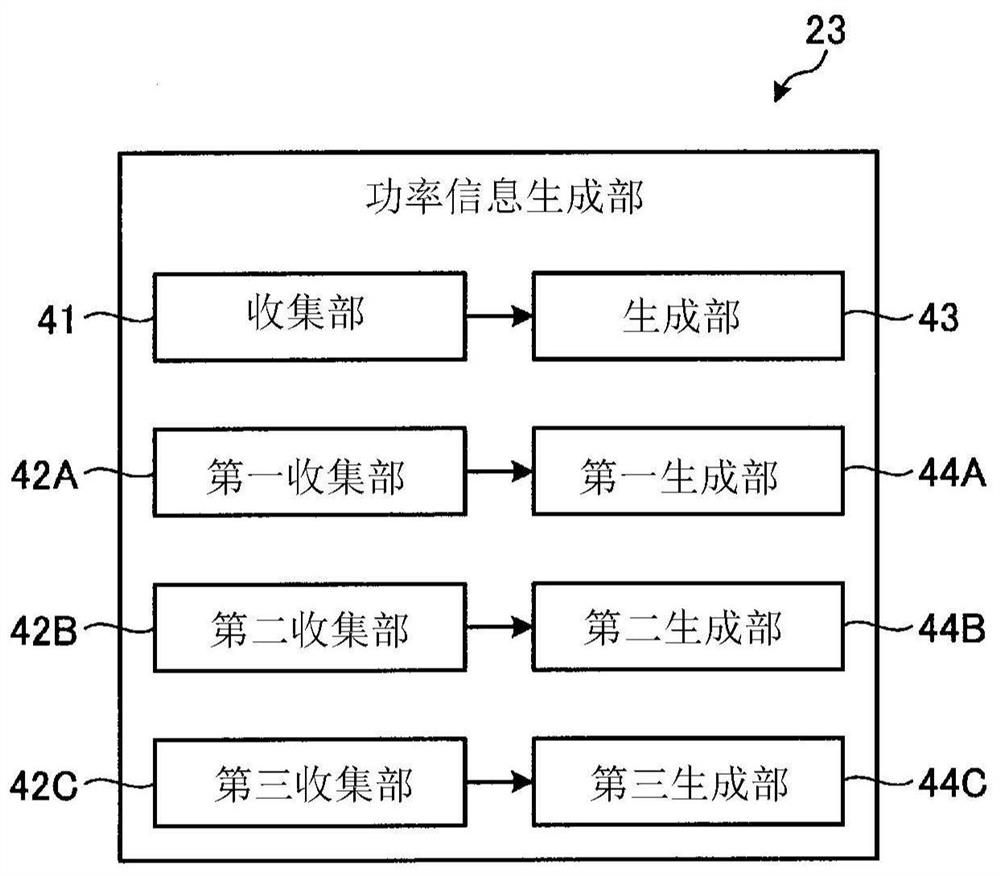
[0093] Figure 7 It is a block diagram showing an example of the power information generation unit 23 of the second embodiment. Figure 7 The illustrated power information generation section 23 includes a fourth collection section 42D in place of the third collection section 42C, and includes a fourth g...
no. 3 approach
[0108] Figure 9 It is a block diagram showing an example of the power information generation unit 23 of the third embodiment. When the first base station 2A is a base station of an LTE cell, the first correction amount and the second correction amount are not required. exist Figure 9 In the illustrated power information generation unit 23, since the first correction amount and the second correction amount are unnecessary, the first collection unit 42A, the second collection unit 42B, the first generation unit 44A, and the second generation unit 44B are deleted. Further, the power information generation unit 23 causes the generation unit 43 to generate the parameters, and causes the fourth generation unit 44D to generate the fourth correction amount.
[0109] Figure 10 It is a block diagram showing an example of the transmission power control unit 67 of the third embodiment. exist Figure 10 In the illustrated transmission power control unit 67, since the first correcti...
PUM
 Abstract
Description
Claims
Application Information
 - R&D
- Intellectual Property
- Life Sciences
- Materials
- Tech Scout
- Unparalleled Data Quality
- Higher Quality Content
- 60% Fewer Hallucinations
Browse by: Latest US Patents, China's latest patents, Technical Efficacy Thesaurus, Application Domain, Technology Topic, Popular Technical Reports.
© 2025 PatSnap. All rights reserved.Legal|Privacy policy|Modern Slavery Act Transparency Statement|Sitemap|About US| Contact US: help@patsnap.com