Signal modulation circuit
A signal modulation and signal technology, applied in the field of transmitters, can solve problems such as complex circuit structure
- Summary
- Abstract
- Description
- Claims
- Application Information
AI Technical Summary
Problems solved by technology
Method used
Image

Examples
no. 1 example
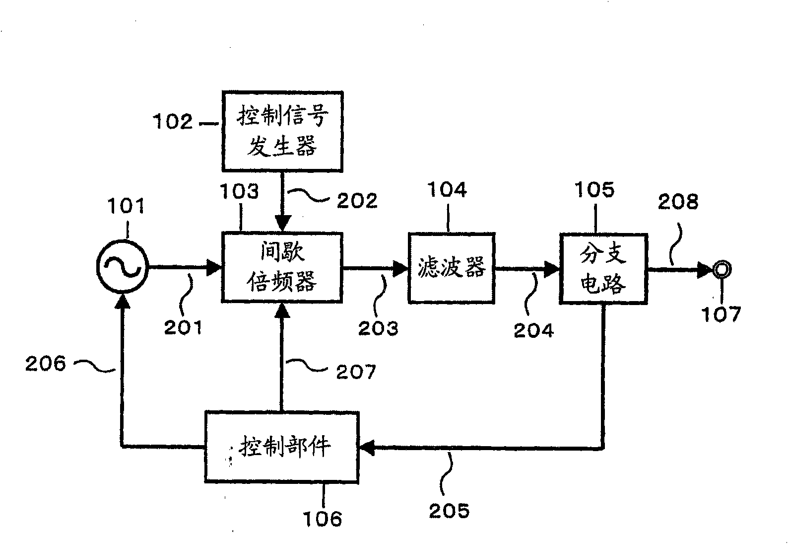
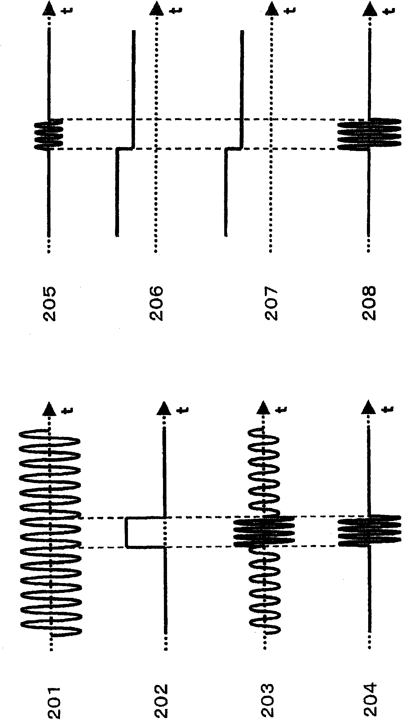
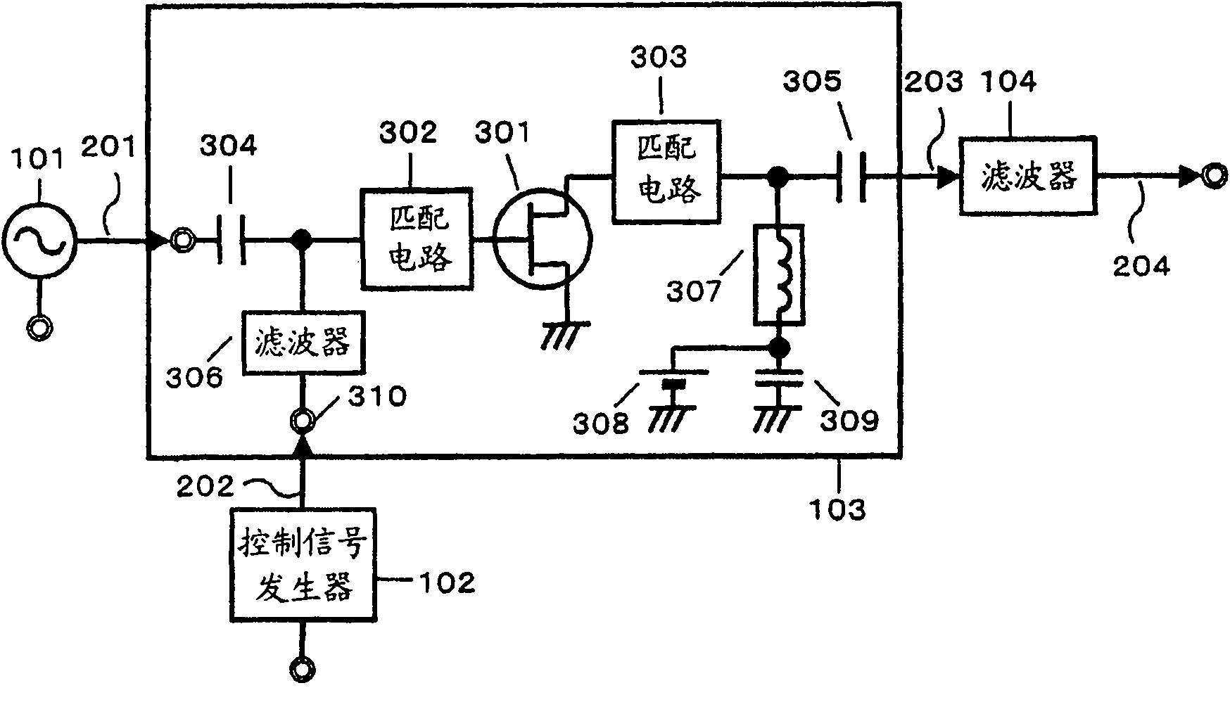
[0087] figure 1 is a block diagram of the communication device in the first embodiment of the present invention. figure 1 The transmitter shown includes an oscillator 101 , a control signal generator 102 , an intermittent frequency multiplier 103 , a filter 104 , a branch circuit 105 , a control component 106 and an output port 107 . The oscillator 101 and the intermittent frequency multiplier 103 are active circuits composed of active elements.
[0088] Hereafter, active elements will be discussed as FETs (Field Effect Transistors). The frequency multiplier of the intermittent frequency multiplier is n (n: a positive integer). In the following description, the desired frequency of the output signal of the oscillator is f0, and the intermittent frequency multiplier is a frequency multiplier by 2 (dual). The signal waveform of the control signal output from the control signal generator 102 is arbitrary, but will be discussed with a pulse waveform hereinafter.
[0089]A co...
no. 2 example
[0148] Figure 10 is a block diagram showing the structure of a pulse generator capable of generating a high on / off ratio pulse signal and capable of adjusting a power level in the second embodiment of the present invention. The second embodiment differs from the first embodiment in that a switch 1001 is provided instead of a branch circuit 105 , and a control section 106 includes a detector 1002 and a control section 1003 .
[0149] Figure 10 The structure shown is a transmitter-receiver. The transmitter includes an oscillator 101 , a control signal generator 102 , an intermittent frequency multiplier 103 and a filter 104 . The receiver comprises a detector 1002 and a control part 1003 . The transmitter and receiver are connected by a switch 1001 . Control section 1003 controls oscillator 101 and intermittent frequency multiplier 103 based on the waveform detected by detector 1002 included in the receiver. The control method is as described in the first embodiment.
[...
no. 3 example
[0156] Figure 11 is a block diagram showing the structure of a pulse generator capable of generating a high on / off ratio pulse signal and capable of adjusting a power level in the third embodiment of the present invention. The difference between the third embodiment and the first embodiment is that a switch 1001 is provided to replace the branch circuit 105, the control part 106 includes a mixer 1101 and a control part 1102, and an intermittent frequency multiplier 103 is provided between the oscillator 101 and the mixer 1101 is used to operate the mixer. As the intermittent frequency multiplier 103, a known circuit is used.
[0157] Figure 11 The structure shown is the same transmitter-receiver as the second embodiment. The transmitter includes an oscillator 101 , a control signal generator 102 , an intermittent frequency multiplier 103 and a filter 104 . The receiver includes a mixer 1101 and a control part 1102 . The transmitter and receiver are connected by a switch...
PUM
 Abstract
Description
Claims
Application Information
 - R&D
- Intellectual Property
- Life Sciences
- Materials
- Tech Scout
- Unparalleled Data Quality
- Higher Quality Content
- 60% Fewer Hallucinations
Browse by: Latest US Patents, China's latest patents, Technical Efficacy Thesaurus, Application Domain, Technology Topic, Popular Technical Reports.
© 2025 PatSnap. All rights reserved.Legal|Privacy policy|Modern Slavery Act Transparency Statement|Sitemap|About US| Contact US: help@patsnap.com