Nano fluid power generation method, an electrolytic tank device and a nano porous membrane
A nano-porous and nano-fluid technology, applied in the direction of generators/motors, generators that convert kinetic energy into electrical energy, electrical components, etc., can solve problems that have not yet been reported in literature and patents, and achieve good practicability, high application value, The effect of low pollution
- Summary
- Abstract
- Description
- Claims
- Application Information
AI Technical Summary
Problems solved by technology
Method used
Image

Examples
Embodiment 1
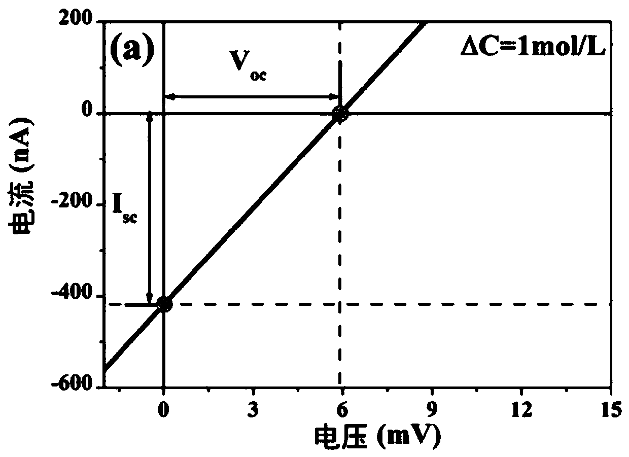
[0062] Example 1 Effect of ion concentration gradient difference on nanofluid power generation
[0063] 1) Preparation of PAAM
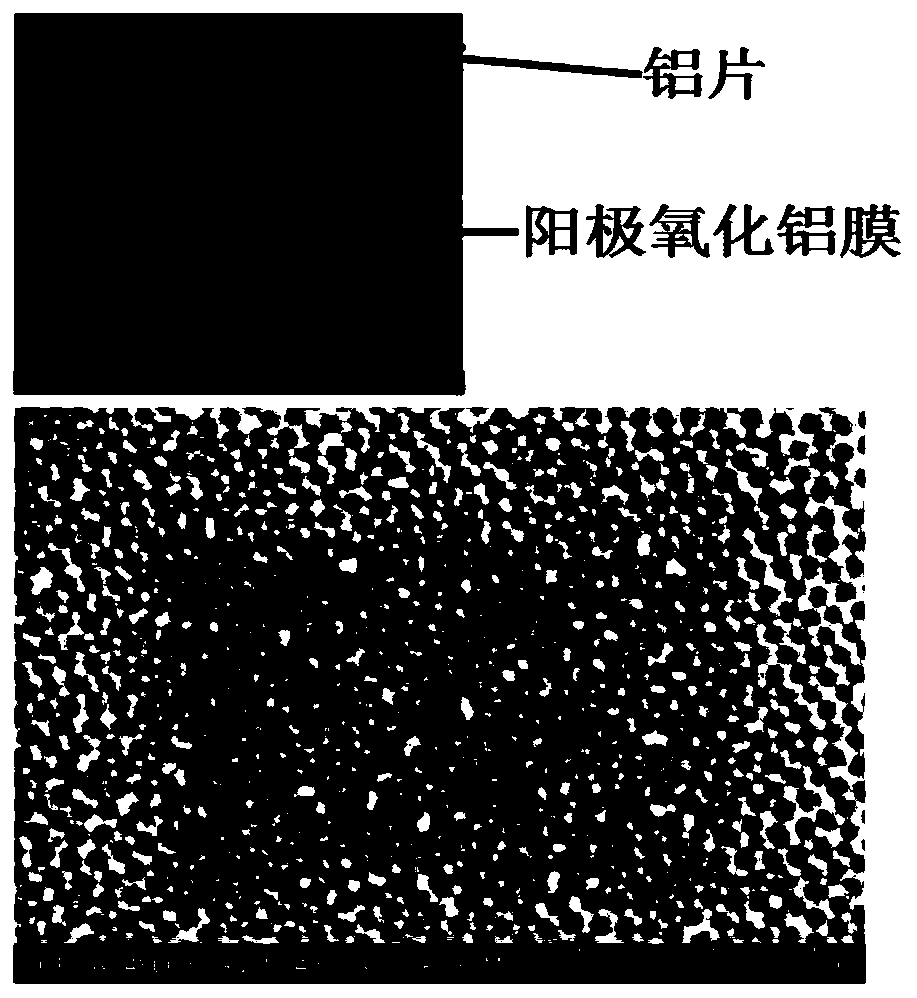
[0064] First anodize the polished aluminum sheet with a purity of 99.99% for 6 hours, then soak it in chromic acid for 12 hours to remove the primary oxide layer, then perform secondary anodic oxidation for 1 hour, and then use saturated copper chloride solution to remove the aluminum oxide film Clean the unreacted aluminum on the back, and use phosphoric acid to pass through holes for about 100 minutes to prepare a circular PAAM with a diameter of 1 cm and a thickness of 4.4 μm;
[0065] Wherein, the anodic oxidation uses a 0.4 mol / L oxalic acid solution, a constant voltage of 30V, and a constant temperature of 10°C.
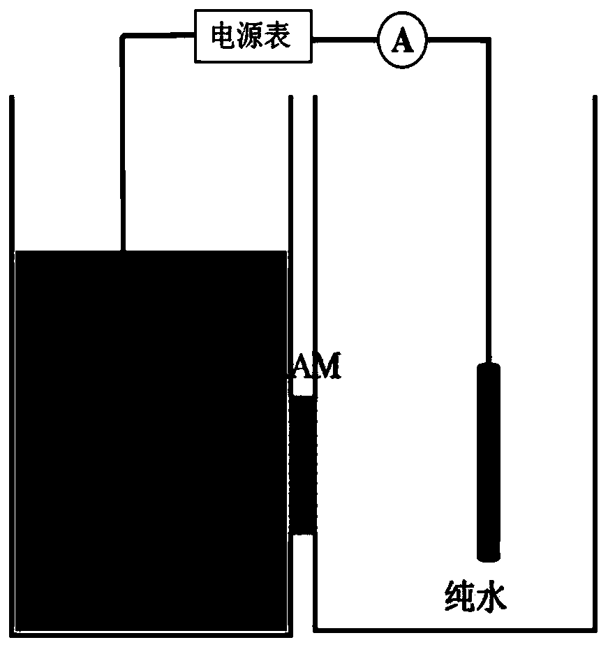
[0066] 2) Assembly of the electrolytic cell
[0067] The PAAM prepared in 1) was fixed at the openings (completely covered) of the pool shells with two side openings in the middle, and an equal amount of KCl solution and pure water ...
Embodiment 2
[0076] Example 2 Effect of Red Ink Modified PAAM on Nanofluid Power Generation
[0077] 1) Preparation of red ink modified PAAM
[0078] After preparing PAAM using the same method as in Example 1, use 3.05×10 -5 g / mL red ink solution for about 1 month.
[0079] 2) Assembly of the electrolytic cell
[0080] Same as Example 1, wherein the concentration of KCl solution is 1mol / L.
[0081] 3) Measurement of volt-ampere characteristic curve
[0082] Same as Example 1.
[0083] 4) Analysis of results
[0084] The SEM image of the PAAM surface after the red ink modification prepared by the present embodiment is as follows Figure 9 shown. Visible, with figure 2 In contrast, PAAM soaked in red ink for a long time formed a new nanoporous membrane structure.
[0085] The volt-ampere characteristic curve measured in this embodiment is as follows Figure 10 shown. It can be seen from the figure that when the applied voltage is zero, the current value is 511.55nA greater than z...
Embodiment 3
[0086] The influence of the amount of embodiment 3 colloidal particles on nanofluid power generation
[0087] 1) Preparation of PAAM
[0088] Same as Example 1.
[0089] 2) Assembly of the electrolytic cell
[0090] The electrolytic cell was assembled using the same method as in Example 1, wherein the concentration of the KCl solution was 1mol / L, the difference being that, on the KCl solution side, red ink solutions of different concentrations were also added.
[0091] 3) Measurement of volt-ampere characteristic curve
[0092] Same as Example 1.
[0093] 4) Analysis of results
[0094] This embodiment studies the short-circuit current, open-circuit voltage and maximum output power under different red ink solution concentrations, such as Figure 11-13 shown (where Figure 13 The dotted line in represents the power generation without colloidal particles). When the red ink solution concentration is 2.6×10 -5 ~4.2×10 -5 In the g / mL range, good results can be obtained; when...
PUM
 Abstract
Description
Claims
Application Information
 - R&D
- Intellectual Property
- Life Sciences
- Materials
- Tech Scout
- Unparalleled Data Quality
- Higher Quality Content
- 60% Fewer Hallucinations
Browse by: Latest US Patents, China's latest patents, Technical Efficacy Thesaurus, Application Domain, Technology Topic, Popular Technical Reports.
© 2025 PatSnap. All rights reserved.Legal|Privacy policy|Modern Slavery Act Transparency Statement|Sitemap|About US| Contact US: help@patsnap.com