
A boundary scanning structure and an IEEE 1500 Wrapper conversion interface

A technology of boundary scan and conversion interface, which is applied to the architecture with a single central processing unit, instruments, general-purpose stored program computers, etc., and can solve problems such as unguaranteed, insufficient access to complex system components, long test time, etc.

Active Publication Date: 2019-06-14
GUILIN UNIV OF ELECTRONIC TECH
View PDF7 Cites 2 Cited by
  • Summary
  • Abstract
  • Description
  • Claims
  • Application Information

AI Technical Summary

Problems solved by technology

[0005] But a boundary-scan architecture based entirely on boundary-scan links and TAP (Test Access Port) interfaces without regard to system size is not enough to effectively access components in complex systems
With the increase of NoC scale, the number of internally integrated resource nodes increases, and the resource nodes that realize specific functions need to be designed in advance and pass the design verification, so that the design of resource nodes with predetermined functions conforms to the design idea of ​​IP (Intellectual Property) core , the development of NoC is to build resource nodes by selecting verified IP cores, which simplifies the design process and avoids the design of many underlying circuits. To be able to pass the test, especially a wide variety of resource nodes often require a large number of test vectors, and testing based solely on boundary scan links will result in too long test time

Method used


Image

  • A boundary scanning structure and an IEEE 1500 Wrapper conversion interface
  • A boundary scanning structure and an IEEE 1500 Wrapper conversion interface
  • A boundary scanning structure and an IEEE 1500 Wrapper conversion interface

Examples


Embodiment Construction

[0024] Embodiments of the present invention are described below through specific examples, and those skilled in the art can easily understand other advantages and effects of the present invention from the content disclosed in this specification. The present invention can also be implemented or applied through other different specific implementation modes, and various modifications or changes can be made to the details in this specification based on different viewpoints and applications without departing from the spirit of the present invention. It should be noted that, in the case of no conflict, the following embodiments and features in the embodiments can be combined with each other.

[0025] It should be noted that the diagrams provided in the following embodiments are only schematically illustrating the basic ideas of the present invention, and only the components related to the present invention are shown in the diagrams rather than the number, shape and shape of the compo...


PUM


Abstract

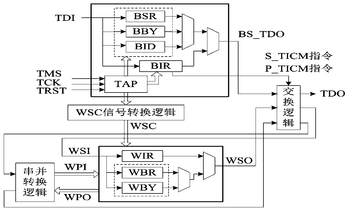
The invention provides a boundary scanning structure and an IEEE 1500 Wrapper conversion interface. The boundary scanning structure comprises a WSC interface control logic module, a switching logic module and a serial-parallel conversion logic module, and the WSC interface control module is connected between a Wrapper and a boundary scanning structure and is used for testing and controlling the Wrapper; the exchange logic module is connected between the Wrapper and the boundary scanning structure and is used for data exchange between a boundary scanning link and the Wrapper; and the serial-parallel conversion logic module is connected between the exchange logic module and the Wrapper and is used for data exchange between the exchange logic module and the Wrapper interface. According to theinvention, combined application of two compatible test mechanisms of IEEE 1500 Wrapper in the NoC boundary scanning test system in the NoC system is combined; the control mechanism of the boundary scanning structure on the IEEE 1500 Wrapper and the data exchange mechanism between the IEEE 1500 Wrapper and the IEEE 1500 Wrapper are achieved, and the boundary scanning structure can conduct the serial testing and parallel testing on the Wrapper in two working modes to conduct data exchange.

Description

technical field [0001] The invention relates to a conversion interface, in particular to a boundary scan structure and IEEE 1500 Wrapper conversion interface. Background technique [0002] NoC (Network on Chip) is an on-chip network chip designed by referring to computer network technology. The communication architecture composed of routing nodes realizes data routing and packet exchange, and resource nodes realize various resource nodes with different functions through one-to-one communication with routing nodes. In the interactive communication in the communication architecture, the NoC system realizes various complex functions. [0003] Distributed network architecture and integrated circuit multiplexing technology enable NoC to integrate more resource nodes by increasing the scale of the NoC system when faced with increased functional requirements. However, with the increase in system scale, how to deal with possible The test caused by the fault needs to become an urgen...

Claims


Application Information

Patent Timeline
Patent Type & Authority Applications(China)
IPC IPC(8): G06F13/40G06F15/78G06F11/267
Inventor 许川佩蒙超勇张硕全新国王建喜
Owner GUILIN UNIV OF ELECTRONIC TECH
Learn More