
An optical switch and an optical transmission method through the optical switch

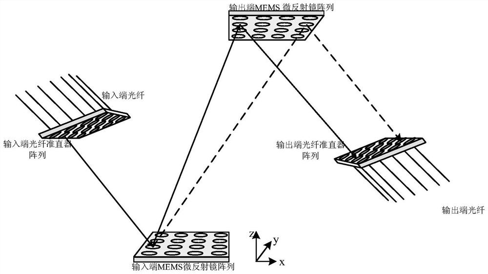
An optical switch and optical signal technology, applied in the field of optical communication, can solve the problems that 3D-MEMS optical switches are difficult to meet the network switching requirements, and it is difficult to increase the maximum rotation capacity of the mirror.

Active Publication Date: 2022-03-29
HUAWEI TECH CO LTD
View PDF5 Cites 0 Cited by
  • Summary
  • Abstract
  • Description
  • Claims
  • Application Information

AI Technical Summary

Problems solved by technology

[0004] Usually the maximum rotatable angle of each mirror on the mirror array is the same, but limited by the technological level, driving principle and other conditions, it is difficult to increase the maximum rotation capability of each mirror, resulting in the current 3D-MEMS It is difficult for optical switches to meet the ever-increasing demand for network switching

Method used


Image

  • An optical switch and an optical transmission method through the optical switch
  • An optical switch and an optical transmission method through the optical switch
  • An optical switch and an optical transmission method through the optical switch

Examples


Embodiment Construction

[0060]Embodiments of the present application provide an optical switch and a transmission method through the optical switch, which can meet greater network switching requirements. The terms "first", "second", "third", "fourth", etc. (if any) in the specification and claims of the present application and the above drawings are used to distinguish similar objects, and not necessarily Used to describe a specific sequence or sequence. It is to be understood that the terms so used are interchangeable under appropriate circumstances such that the embodiments described herein can be practiced in sequences other than those illustrated or described herein. Furthermore, the terms "comprising" and "having", as well as any variations thereof, are intended to cover a non-exclusive inclusion, for example, a process, method, system, product or device comprising a sequence of steps or elements is not necessarily limited to the expressly listed instead, may include other steps or elements not...


PUM

PropertyMeasurementUnit
angleaaaaaaaaaa
refractive indexaaaaaaaaaa

Abstract

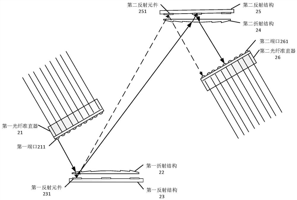
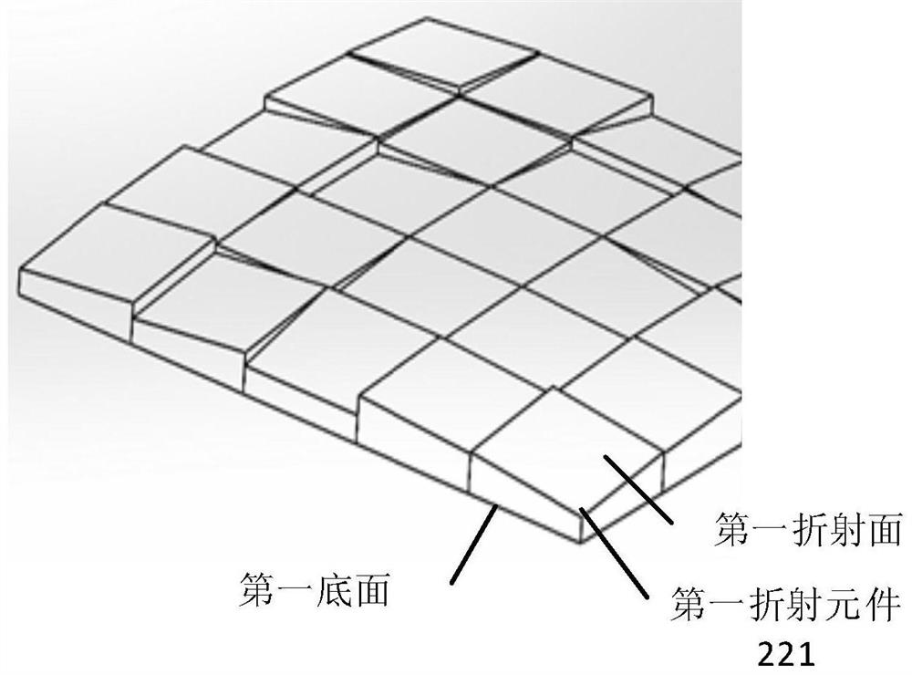
The embodiment of the present application discloses an optical switch and an optical transmission method, which can meet greater network switching requirements. The optical switch in the embodiment of the present application includes: a first fiber collimator, a second fiber collimator, a first refraction structure, a first reflection structure, a second refraction structure, and a second reflection structure, and the first reflection structure includes N The first reflective element, the second reflective structure includes M second reflective elements; the first optical fiber collimator is used to guide the input optical signal to the first refraction structure; the first refraction structure is used to guide the input optical signal from the first optical fiber collimator The optical signal is refracted to the first reflective structure, and the optical signal reflected by the first reflective structure is refracted to the second refraction structure; the second refraction structure is used to refract the optical signal from the first refraction structure to the second reflective structure, and The light signal reflected by the second reflection structure is refracted to the second fiber collimator; the second fiber collimator is used to output the light signal from the second refraction structure.

Description

technical field [0001] The present application relates to the field of optical communication, and in particular to an optical switch and an optical transmission method through the optical switch. Background technique [0002] From the current trend of information technology development, the construction of large-capacity high-speed integrated network and data center has become an inevitable trend of information technology development. As the complexity of the optical network of the metropolitan area network continues to increase, there are often a large number of wavelength division multiplexed (wavelength division multi-plex, WDM) optical signals from different directions at the backbone node of the metropolitan area network. in different directions. [0003] Optical cross-connect (optical cross connect, OXC) components are key components that constitute large-capacity optical networks and data center networks. Among them, the use of three-dimensional microelectromechanica...

Claims


Application Information

Patent Timeline
Patent Type & Authority Patents(China)
IPC IPC(8): G02B6/35
CPCG02B6/352G02B6/3524G02B6/3518G02B6/3556
Inventor 张鹏
Owner HUAWEI TECH CO LTD
Learn More