An Array Micro Gas Compressor

A gas compressor and array technology, applied in the field of array micro gas compressors, can solve the problems of high output pressure, large output flow, low output flow and pressure, etc., and achieve high gas supply capacity and high volume energy density. Effect

Active Publication Date: 2020-05-26
ZHEJIANG NORMAL UNIVERSITY
View PDF12 Cites 0 Cited by
  • Summary
  • Abstract
  • Description
  • Claims
  • Application Information

AI Technical Summary

Problems solved by technology

Although the structure, principle and performance of the above-mentioned gas compression and delivery devices are quite different, they all use the bending deformation of the wafer-type piezoelectric vibrator under the action of an electric field to realize the gas drive, and the volume change of the compression chamber caused by the bending deformation of the piezoelectric vibrator The volume is relatively small, and the output flow and pressure that can be realized by the existing piezoelectric gas compression device are still very low, especially the large output flow and high output pressure cannot be obtained at the same time, so the popularization and application are restricted to a certain extent

Method used


Image

  • An Array Micro Gas Compressor
  • An Array Micro Gas Compressor
  • An Array Micro Gas Compressor

Examples


Embodiment Construction

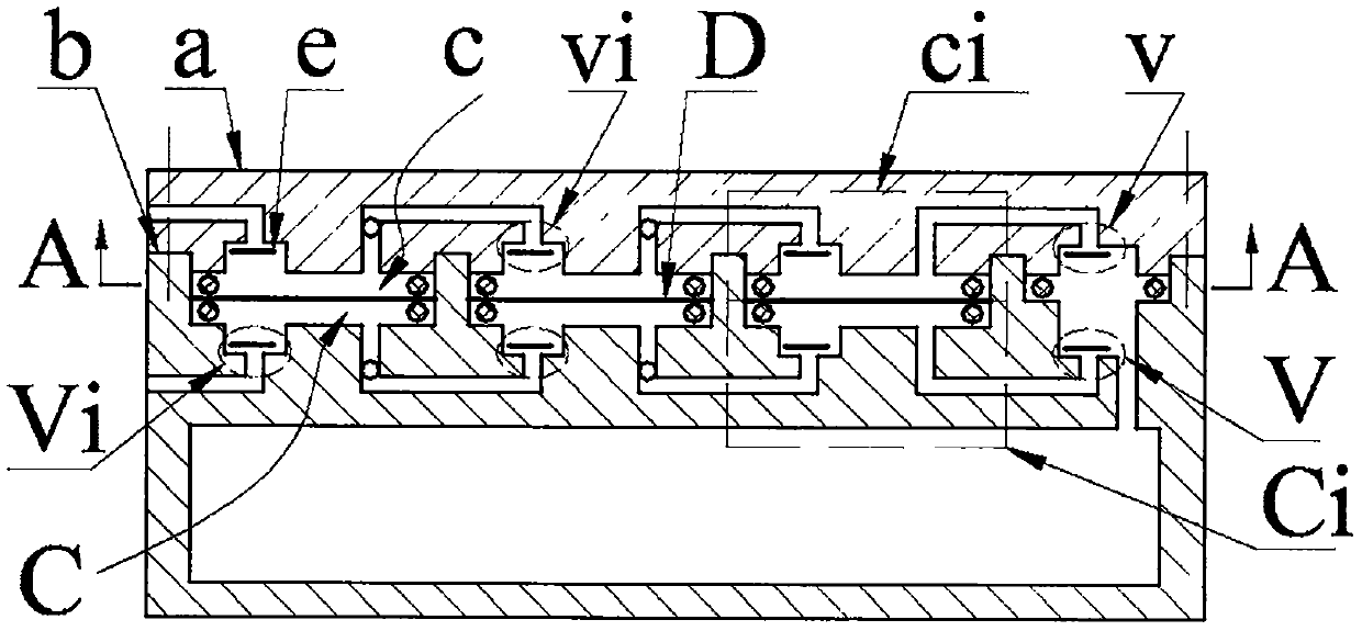
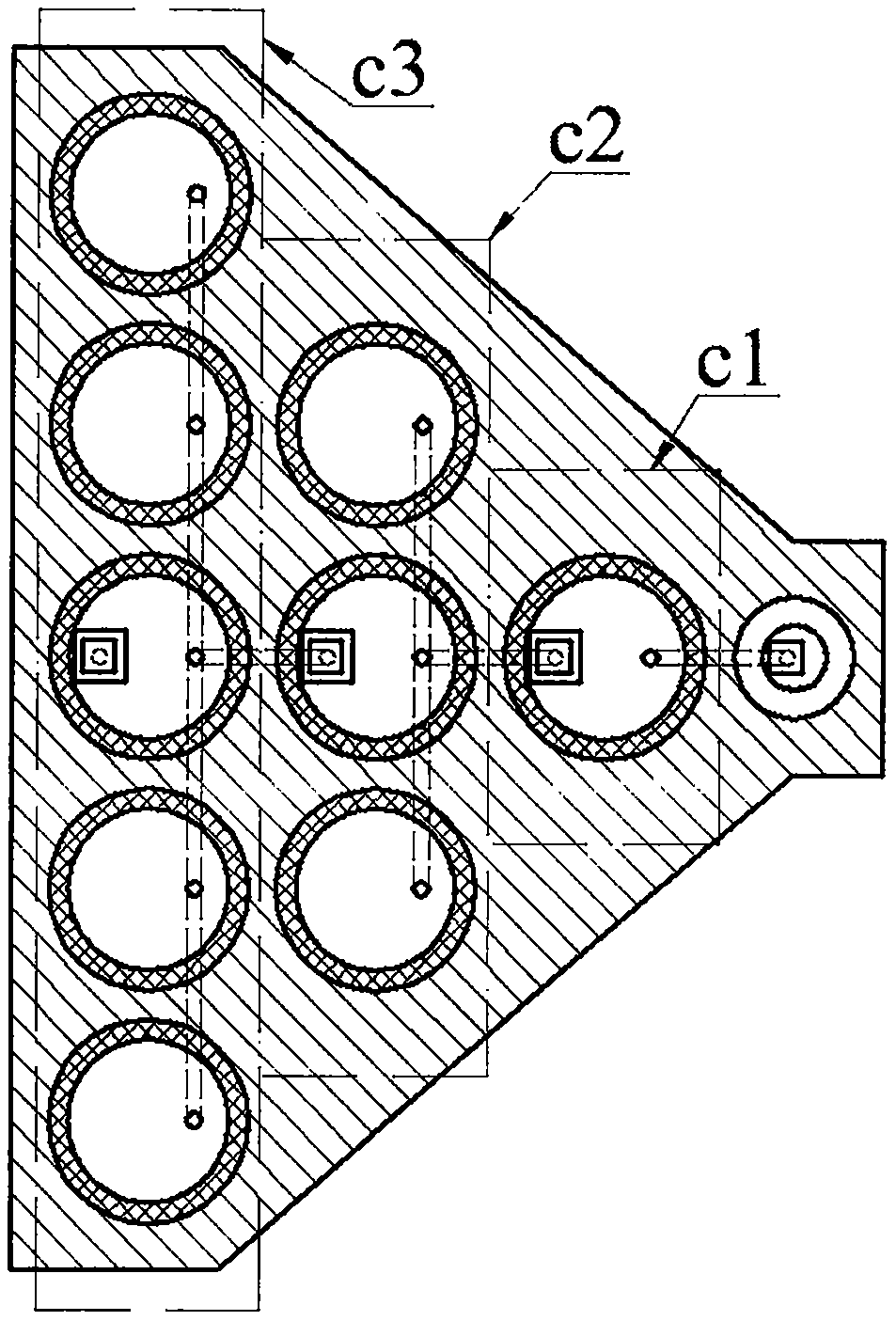
[0017] An array micro gas compressor of the present invention is composed of an upper cover a, a box body b, a one-way valve e and a driver D. The upper cover a is provided with an upper air inlet a1, a boss a3 with an upper outlet a6, and at least two circular platform groups Ai, and the number of circular platform a2 contained in each circular platform group Ai increases sequentially from right to left; in each circular platform group Ai One round table a2 is provided with an upper inlet a4 and an upper air outlet a5, and the other round table a2 is only provided with an upper air hole a8; the upper inlet a4 in the leftmost round table group Ai communicates with the upper air inlet a1, and the rightmost round table group Ai The upper air outlet a5 in the middle is connected with the upper outlet a6; the upper air outlet a5 and the upper air hole a8 in the same round table group Ai are connected through the upper communication hole a7, and the upper inlet a4 and the upper outl...


PUM


Abstract

The invention belongs to the field of micro-fluid transmission and control, and particularly relates to an array type micro gas compressor. An upper cover provided with circular truncated cone groupsis arranged on a box body provided with body cavity groups, an upper inlet and outlet cavity of the upper cover, a lower inlet and outlet cavity of the box body and one-way valves arranged in the upper inlet and outlet cavity of the box body correspondingly form an upper inlet and outlet valve and a lower inlet and outlet valve; bosses of the upper cover are arranged in hole cavities of the box body, and the upper outlet cavity of the upper cover communicates with the lower outlet cavity of the box body and a gas storage chamber, the circular truncated cones of the upper cover press the driverinto the body cavity of the box body through sealing rings, the driver is composed of two piezoelectric vibrators and an annular gasket, and the piezoelectric vibrators are formed by bonding substrates and piezoelectric sheets; the driver and the sealing rings are connected with the upper cover and the box body to form an upper compression cavity and a lower compression cavity, the upper compression cavity and the lower compression cavity in the same body cavity group are respectively connected into an upper compression cavity group and a lower compression cavity group, the upper compressioncavity group and the lower compression cavity group are respectively connected into an upper compression unit and a lower compression unit, and the upper compressing unit and the lower compressing unit are connected in parallel; and in the working process, upper compressing units and lower compressing units are used for carrying out step-by-step accumulative compression on gas, and then alternately arranging the gas into the gas storage chamber.

Description

technical field [0001] The invention belongs to the field of trace gas transmission and control, in particular to an array type micro gas compressor. Background technique [0002] Micro gas compression and delivery devices are also known as micro gas compressors, gas pumps, gas compression devices, etc., and are mainly used in gas sampling, gas circulation and supply, jet cooling, negative pressure maintenance, gas charging, oxygenation and many other aspects. According to the working principle, commonly used gas compression devices can be divided into diaphragm type, electromagnetic type, impeller type, piston type, etc. The common feature is that they all include mechanical transmission parts, so the structure is complex, the volume, weight and power consumption are large, and There is large noise and electromagnetic interference, which is not convenient for the miniaturization and integration of the structure, and its application in the field of micro-electromechanical sy...

Claims


Application Information

Patent Timeline
IPC IPC(8): F04B45/047F04B39/10
Inventor 蒋永华柴超辉王淑云常正方杨泽盟郑佳佳程光明
Owner ZHEJIANG NORMAL UNIVERSITY
Why Eureka
Try Eureka