An electrical cabinet with a dehumidification mechanism

A technology for electrical cabinets and cabinets, applied in the field of electrical cabinets, can solve problems such as short circuits, corrosion of electrical components, accidents, etc., and achieve the effect of increasing condensation effect and increasing contact area.

Active Publication Date: 2021-04-02
安徽辉宝智能装备有限责任公司
View PDF4 Cites 0 Cited by
  • Summary
  • Abstract
  • Description
  • Claims
  • Application Information

AI Technical Summary

Problems solved by technology

A variety of electrical accessories are usually installed in the electrical cabinet, so the requirements for circuit safety are relatively high, especially if the electrical cabinet is in a relatively humid environment for a long time, it will not only corrode the electrical components, but also easily cause circuit short circuit or other accidents. Some electrical cabinets just use some desiccant or use fans or heating elements to dehumidify, which often cannot fundamentally solve the problem of humidity

Method used


Image

  • An electrical cabinet with a dehumidification mechanism
  • An electrical cabinet with a dehumidification mechanism
  • An electrical cabinet with a dehumidification mechanism

Examples


Embodiment Construction

[0027] The following will clearly and completely describe the technical solutions in the embodiments of the present invention with reference to the accompanying drawings in the embodiments of the present invention. Obviously, the described embodiments are only some, not all, embodiments of the present invention. Based on the embodiments of the present invention, all other embodiments obtained by persons of ordinary skill in the art without making creative efforts belong to the protection scope of the present invention.

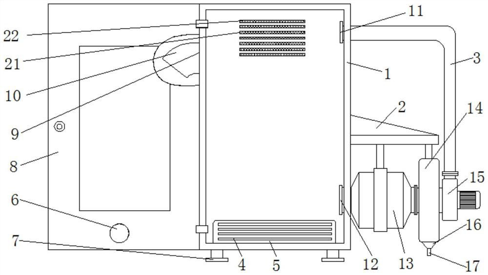
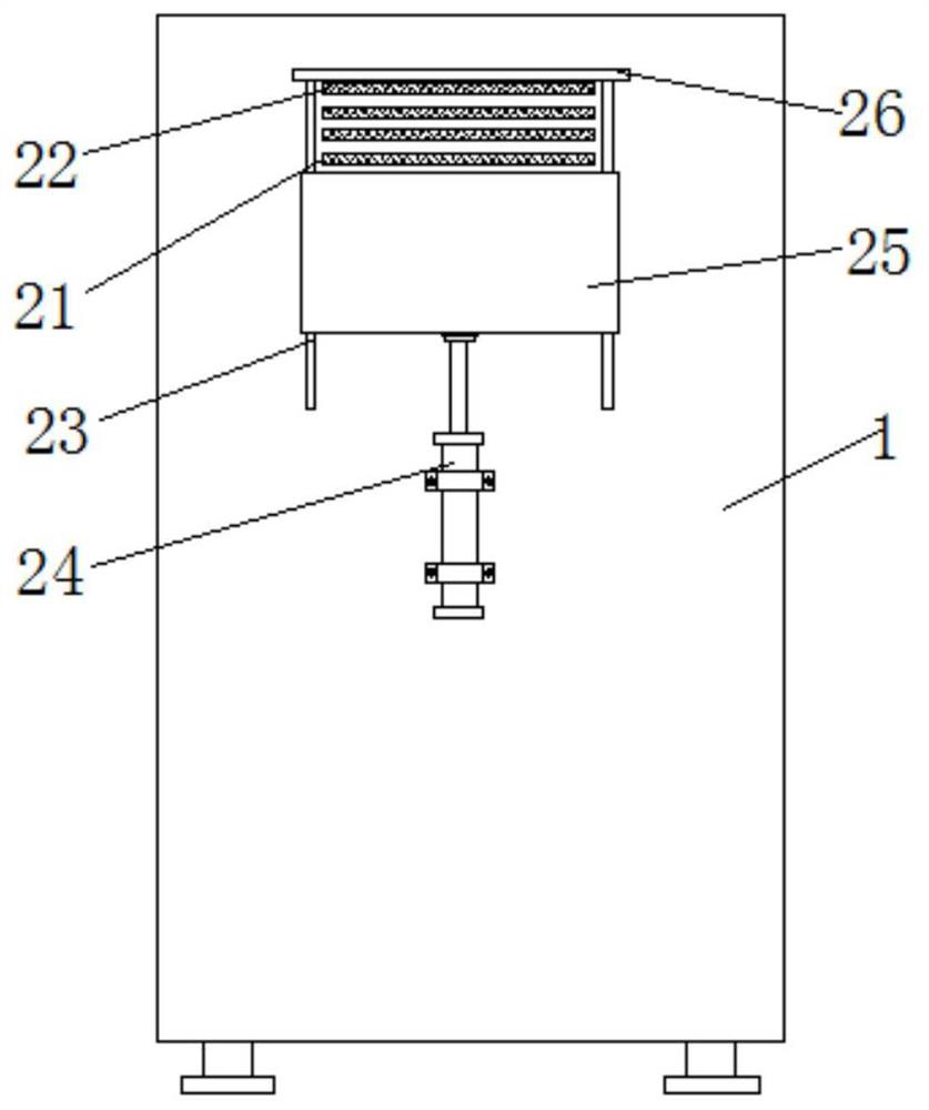
[0028] Such as Figure 1-6 As shown, an electrical cabinet with a dehumidification mechanism includes a cabinet body 1 and a cabinet door 8 hinged on one side of the cabinet body 1, and a plurality of cooling holes 21 are provided on the rear side wall of the cabinet body 1, and the On the side wall at one end of the cabinet body 1, there is a wiring port 9, and the four corners of the bottom end of the cabinet body 1 are fixed with support legs 7, and the upp...


PUM


Abstract

The invention discloses an electrical cabinet with a dehumidification mechanism. The electrical cabinet comprises a cabinet body and a cabinet door hinged to one side of the cabinet body; a pluralityof heat dissipation holes are formed in the rear side wall of the cabinet body, and a wiring port is formed in the side wall of one end of the cabinet body; supporting legs are fixed at the four corners of the bottom end of the cabinet body; an air discharging opening and an air extracting opening are formed in the upper end and the lower end of the side wall of the cabinet body respectively; theouter side of the air extracting opening is communicated with a dehumidification box, and a fixed frame is further fixedly arranged on the outer side wall of the cabinet body; the upper end of the dehumidification box is fixedly connected to the fixed frame; the air outlet of the dehumidification box is connected with an air suction pump, and the air outlet in the upper end of the air suction pumpis communicated with an air delivery pipe, and the other end of the air delivery pipe is in sealing connection with the gas discharging opening in the upper end of the side wall of the cabinet body;a semiconductor condensation piece is arranged in the dehumidification box, and a downward water outlet pipe is further communicated with the center of the bottom end of the dehumidification box. According to the electrical cabinet, the dehumidification box with the built-in semiconductor condensation piece and the air suction pump are arranged on one side of the electrical cabinet, so that the wet air in the electrical cabinet can be cyclically replaced into relatively-dried air.

Description

technical field [0001] The invention relates to the technical field of electrical cabinets, in particular to an electrical cabinet with a dehumidification mechanism. Background technique [0002] The electrical cabinet is a cabinet made of steel to protect the normal operation of components. The materials for making electrical cabinets are generally divided into two types: hot-rolled steel plates and cold-rolled steel plates. Compared with hot-rolled steel sheets, cold-rolled steel sheets are softer and more suitable for the production of electrical cabinets. Electrical cabinets are widely used mainly in chemical industry, environmental protection industry, power system, metallurgical system, industry, nuclear power industry, fire safety monitoring, transportation industry and so on. A variety of electrical accessories are usually installed in the electrical cabinet, so the requirements for circuit safety are relatively high, especially if the electrical cabinet is in a re...

Claims


Application Information

Patent Timeline
Patent Type & Authority Patents(China)
IPC IPC(8): H05K5/02H05K7/20B01D53/26B01D49/00
Inventor 李贵
Owner 安徽辉宝智能装备有限责任公司
Why Eureka
Try Eureka