Automatic PIN disassembly machine

An automatic, rack-mounted technology, applied in the direction of multi-layer circuit manufacturing, etc., can solve the problems of high labor intensity, low efficiency, easy to damage circuit boards, etc., and achieve the effect of high disassembly efficiency and simple structure

Pending Publication Date: 2019-06-11
KUNSHAN JUHONG MACHINERY TECH
View PDF0 Cites 5 Cited by
  • Summary
  • Abstract
  • Description
  • Claims
  • Application Information

AI Technical Summary

Problems solved by technology

At present, in many cases, the dismantling of the PIN pin is still carried out manually or semi-automatically, that is, the PIN pin is taken out by tapping with a hammer. This method is labor-intensive, low in efficiency, and easily damages the circuit board.
Or use manual hydraulic unpinning method, which is labor-intensive and low-efficiency

Method used


Image

  • Automatic PIN disassembly machine
  • Automatic PIN disassembly machine
  • Automatic PIN disassembly machine

Examples


Embodiment

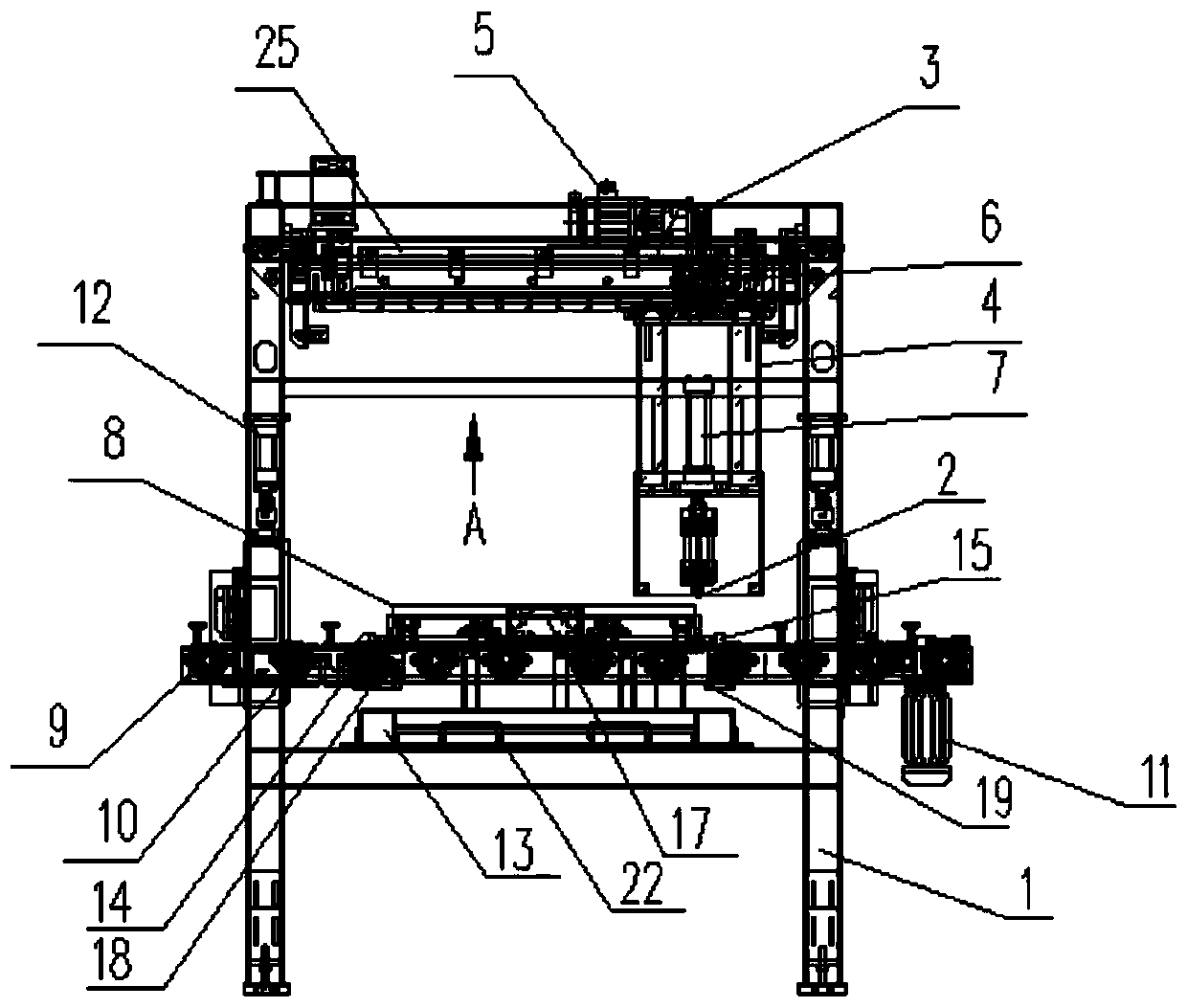
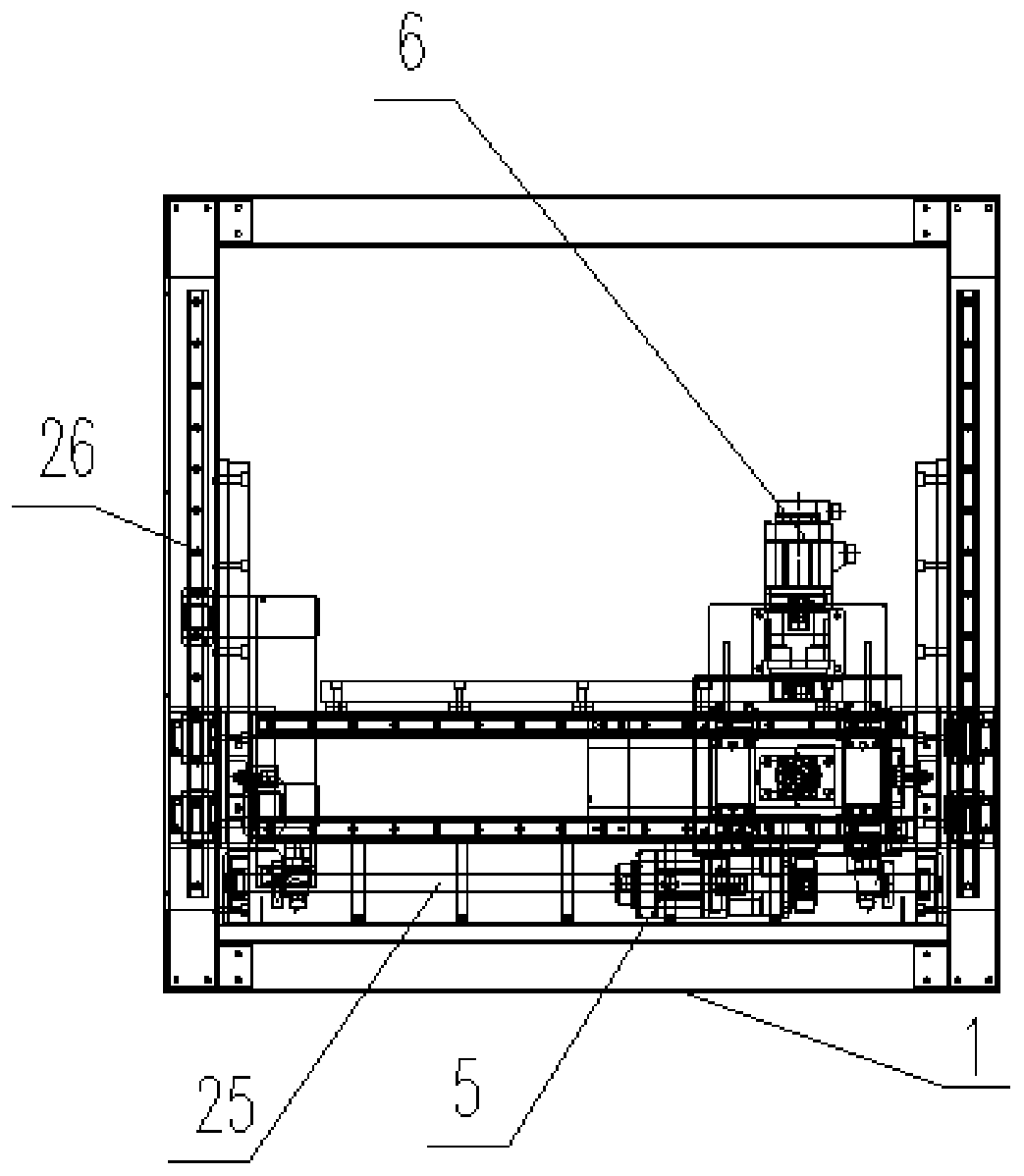
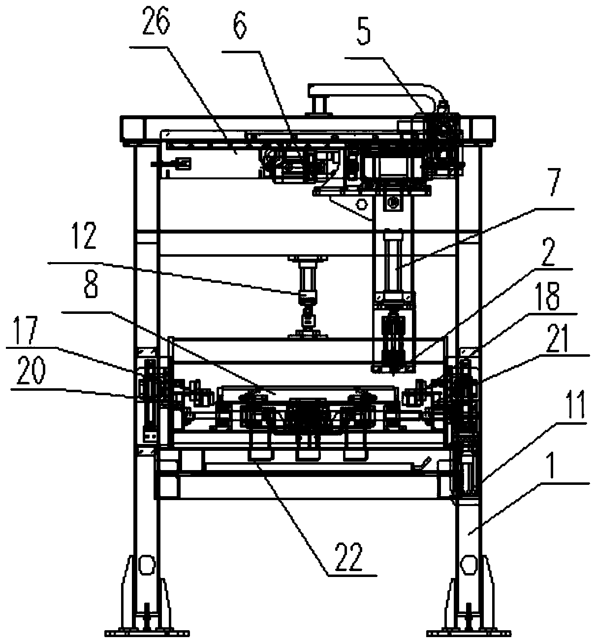
[0021] Embodiment: An automatic PIN needle dismantling machine, including a frame 1, a ejector pin 2, a slider 3 in the X direction, a slider 4 in the Y direction, a plate position correction device, a code scanner, a drive device in the X direction 5, and a The driving device 6, the longitudinal driving device 7 and the control system, the X direction and the Y direction are two directions perpendicular to each other on the horizontal plane, the X direction slider 3 is positioned on the frame 1 that can slide along the X direction, and the Y direction slides The block 4 can be slid along the Y direction and positioned on the X direction slider 3, and the ejector pin 2 can be longitudinally slid on the Y direction slider 4, and the plate position correction device is installed on the frame 1, and the plate position correction device can Calibrate the position of the PIN plate 8 to be removed in the rack 1, the code scanner can read the information in the barcode 27 on the surfa...


PUM


Abstract

The invention discloses an automatic PIN disassembly machine, comprising a rack, a lifting pin, an X direction sliding block, a Y direction sliding block, a plate position calibration device, a code scanner, an X direction drive device, a Y direction drive device, a vertical drive device and a control system. The X direction sliding block can be positioned on the rack in a sliding mode along an Xdirection. The Y direction sliding block can be positioned on the X direction sliding block in the sliding mode along a Y direction. The lifting pin can be mounted on the Y direction sliding block inthe sliding mode along a vertical direction. The plate position calibration device on the rack can correct a position of a to-be-disassembled PIN plate in the rack. The code scanner can read information in a bar code on the to-be-disassembled PIN plate. The code scanner communicates with the control system. The control system drives the X direction sliding block, the Y direction sliding block andthe lifting pin to move through control over the X direction drive device, the Y direction drive device and the vertical drive device. The automatic PIN disassembly machine is simple in structure andhigh in disassembly efficiency. Full automatic disassembly of PINs on the plate can be realized. The plate is not damaged.

Description

technical field [0001] The invention relates to an automatic device, in particular to an automatic PIN needle dismantling machine. Background technique [0002] Multi-layer printed circuit board (Printed Circuit Board, PCB) is formed by heat-pressing layer by layer copper-clad laminates. During lamination, PIN pins are used between layers for positioning. After lamination, insert The PIN needle in the positioning hole is taken out, wherein, the PIN needle is usually a cylindrical metal pin. The operation process of taking out the PIN pin can be called PIN pin dismantling. At present, in many cases, the dismantling of the PIN pin is still performed manually or semi-automatically, that is, the PIN pin is taken out by beating with a hammer. This method is labor-intensive, low in efficiency, and easily damages the circuit board. Or use the manual hydraulic pressure solution pin mode, this method labor intensity is big, and efficiency is low. Contents of the invention [000...

Claims


Application Information

Patent Timeline
Patent Type & Authority Applications(China)
IPC IPC(8): H05K3/46
Inventor 施元中
Owner KUNSHAN JUHONG MACHINERY TECH
Why Eureka
Try Eureka