Three-dimensional ribbed pipe machining cutter bar positioning device with buffer structure

A buffer structure and positioning device technology, applied in positioning devices, metal processing equipment, metal processing machinery parts, etc., can solve the problems of applicability and practicability limitations, affecting processing efficiency, low heat exchange efficiency, etc., and achieve practicality Good, guaranteed processing quality, strong applicability

Inactive Publication Date: 2019-06-11
重庆市融亚换热器科技有限公司
View PDF0 Cites 3 Cited by
  • Summary
  • Abstract
  • Description
  • Claims
  • Application Information

AI Technical Summary

Problems solved by technology

[0002] The heat exchange elements used in the heat exchanger include plain tubes, threaded tubes, finned tubes and corrugated tubes, etc., whose heat exchange efficiency is low, and the ribbed tube is a high-efficiency enhanced tubular heat exchange element, with high heat exchange efficiency , can achieve the purpose of saving energy and reducing consumption and environmental protection. The main structural features of the three-dimensional ribbed tube include the light tube. The ribs are carved on the inner surface of the light tube, thereby forming a three-dimensional structure as a whole, which greatly increases the heat transfer area and improves In order to improve the heat transfer performance, when processing three-dimensional ribbed tubes, the traditional tool bar support frame adopts V-shaped blocks or supporting temples. When the tool bar moves back and forth, it is easy to cause wear of the tool bar. At the same time, fixing the workpiece on the tool bar support frame is also It is more difficult, which will seriously affect the efficiency of processing, and the applicability and practicability are limited

Method used


Image

  • Three-dimensional ribbed pipe machining cutter bar positioning device with buffer structure
  • Three-dimensional ribbed pipe machining cutter bar positioning device with buffer structure

Examples


Embodiment 1

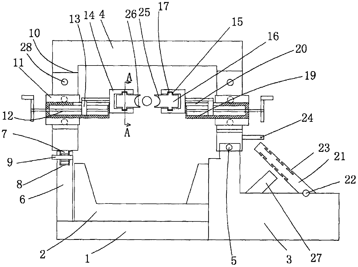
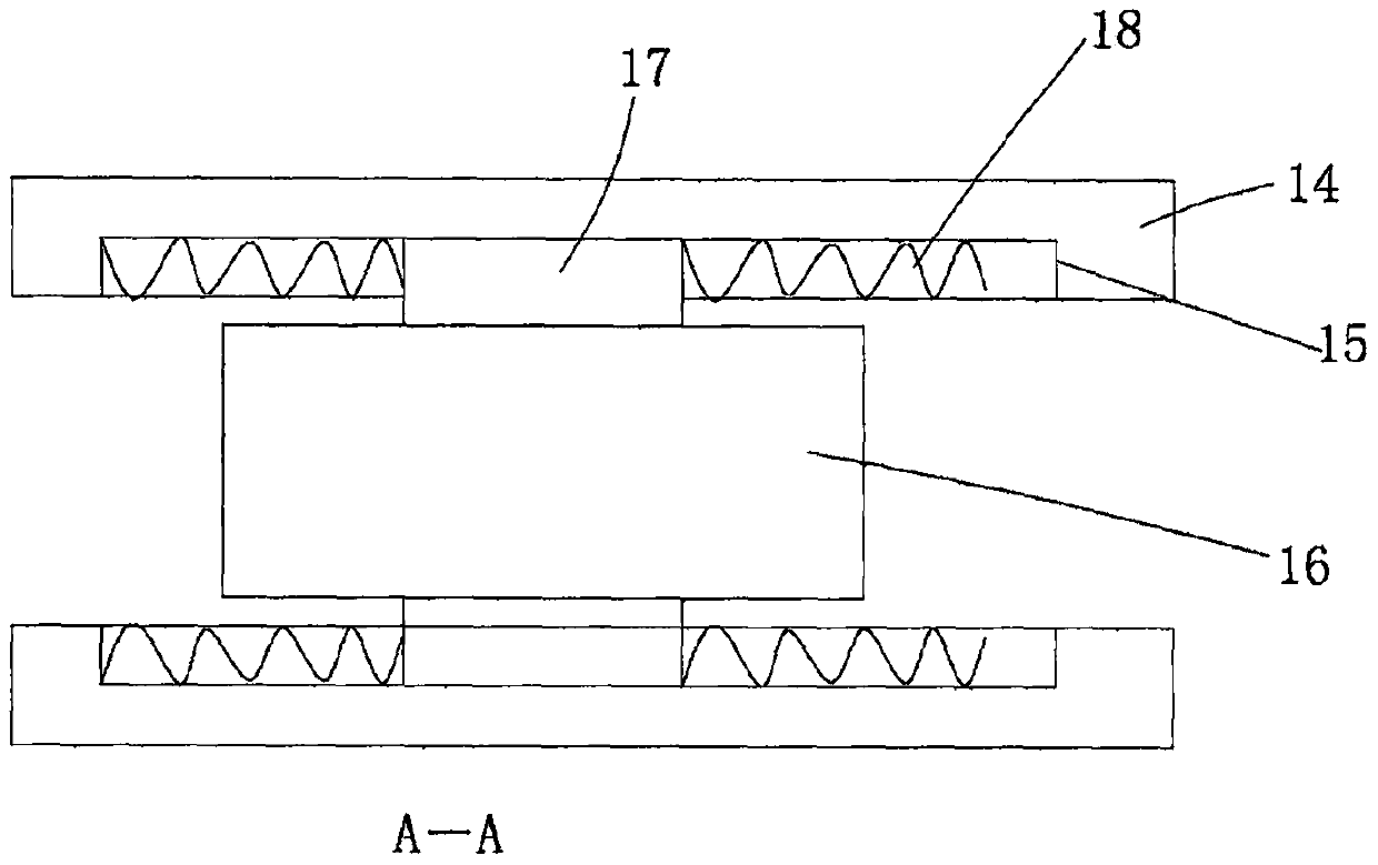
[0016] figure 1 with figure 2 A specific embodiment of the invention is shown in which figure 1 It is a structural schematic diagram of the present invention; figure 2 for figure 1 Middle A-A sectional view.

[0017] See figure 1 with figure 2 , a three-dimensional ribbed tube processing cutter bar positioning device with a buffer structure, comprising a base 1, a workpiece carrier 2 arranged on the base, a limited support 3 is arranged on the side of the base, and a An n-shaped tool bar carrier 4 is provided, one end of the n-shaped tool bar carrier is connected to the connection between the base and the limit support through a pin shaft 5, and a locking convex plate 6 is arranged on the base , the locking convex plate and the limiting support are symmetrically arranged on both sides of the base, and a positioning snap ring 7 is arranged on the other end of the n-shaped tool bar carrier, and a positioning snap ring 7 is arranged on the locking convex plate. The card...


PUM


Abstract

The invention discloses a three-dimensional ribbed pipe machining cutter bar positioning device with a buffer structure. The three-dimensional ribbed pipe machining cutter bar positioning device comprises a base and a workpiece bearing frame arranged on the base, a limiting support is arranged on the side face of the base, an n-shaped cutter bar bearing frame is arranged on the base, a position-clamping protruding plate is arranged on the base, a clamping groove with the open top face is formed in the position-clamping protruding plate, a transverse pin rod is arranged on the position-clampingprotruding plate, a positioning clamping ring is inserted into the clamping groove and positioned through the transverse pin rod, vertical adjusting grooves are formed in two vertical rods of the n-shaped cutter bar bearing frame correspondingly, lifting sliding blocks are arranged in the vertical adjusting grooves, transmission lead screws are transversely arranged in the middles of the liftingsliding blocks, transmission sliding blocks are arranged on the transmission lead screws, and C-shaped clamping blocks are arranged on the transmission sliding blocks. The three-dimensional ribbed pipe machining cutter bar positioning device is reasonable in structural arrangement, the using demands under different situations can be met, the machining efficiency is ensured advantageously, using isstable and reliable, and the three-dimensional ribbed pipe machining cutter bar positioning device is high in applicability and good in practicability.

Description

technical field [0001] The invention belongs to the technical field of three-dimensional rib tube processing equipment, and in particular relates to a three-dimensional rib tube processing cutter bar positioning device with a buffer structure. Background technique [0002] The heat exchange elements used in the heat exchanger include plain tubes, threaded tubes, finned tubes and corrugated tubes, etc., whose heat exchange efficiency is low, and the ribbed tube is a high-efficiency enhanced tubular heat exchange element, with high heat exchange efficiency , can achieve the purpose of saving energy and reducing consumption and environmental protection. The main structural features of the three-dimensional ribbed tube include the light tube. The ribs are carved on the inner surface of the light tube, thereby forming a three-dimensional structure as a whole, which greatly increases the heat transfer area and improves In order to improve the heat transfer performance, when proces...

Claims


Application Information

Patent Timeline
Patent Type & Authority Applications(China)
IPC IPC(8): B23Q3/00
Inventor 何莺
Owner 重庆市融亚换热器科技有限公司
Why Eureka
Try Eureka