Pipeline laser welding machine

A laser welding machine and pipeline technology, applied in laser welding equipment, welding equipment, metal processing equipment, etc., can solve the problems of easy swing, easy breakage of bellows, bending deformation, etc., to avoid rotation, solve fatigue damage, prevent The effect of bending deformation or fracture

Pending Publication Date: 2019-07-19
广东聚金激光技术有限公司
View PDF0 Cites 4 Cited by
  • Summary
  • Abstract
  • Description
  • Claims
  • Application Information

AI Technical Summary

Problems solved by technology

[0002] When the existing gas pipe laser welding machine welds the gas pipe and the pipe joint, it either realizes the welding of the joint by rotating the gas pipe and the pipe joint, or completes the welding by turning the laser welding device around it; When the gas pipe is welded, due to the long length of the gas pipe, it is easy to swing during the rotation process, which is easy to cause bending deformation, especially the corrugated pipe is easy to break; and the laser welding device is used for welding in circles, and the optical fiber is easy to be wound on the equipment , but also prone to fiber damage due to fatigue damage

Method used


Image

  • Pipeline laser welding machine
  • Pipeline laser welding machine
  • Pipeline laser welding machine

Examples


Embodiment Construction

[0022] This part will describe the specific embodiment of the present invention in detail, and the preferred embodiment of the present invention is shown in the accompanying drawings. Each technical feature and overall technical solution of the invention, but it should not be understood as a limitation on the protection scope of the present invention.

[0023] In the description of the present invention, it should be understood that the orientation descriptions, such as up, down, front, back, left, right, etc. indicated orientations or positional relationships are based on the orientations or positional relationships shown in the drawings, and are only In order to facilitate the description of the present invention and simplify the description, it does not indicate or imply that the device or element referred to must have a specific orientation, be constructed and operated in a specific orientation, and thus should not be construed as limiting the present invention.
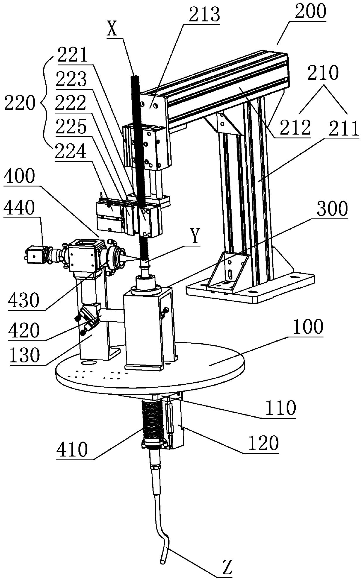
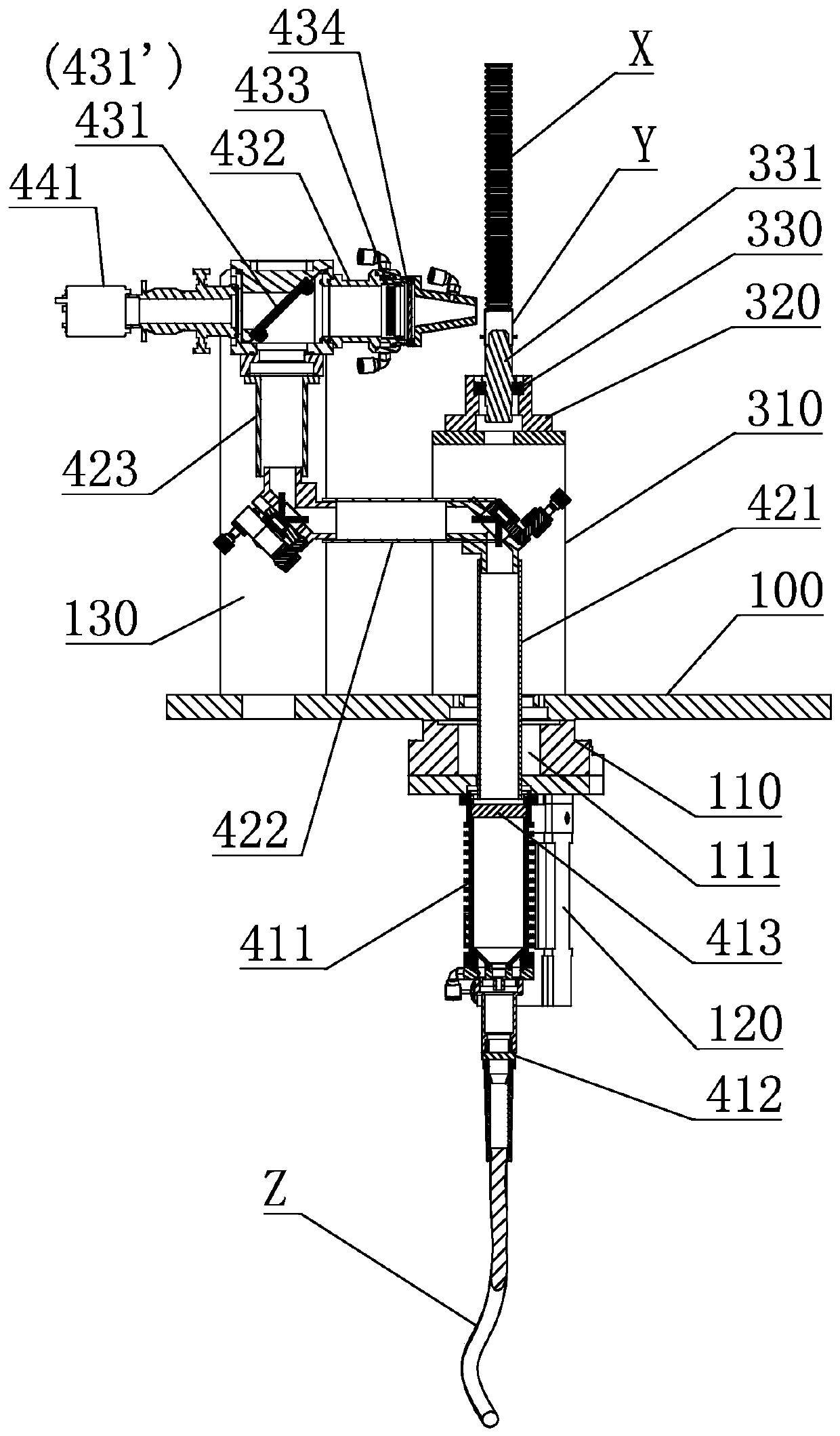
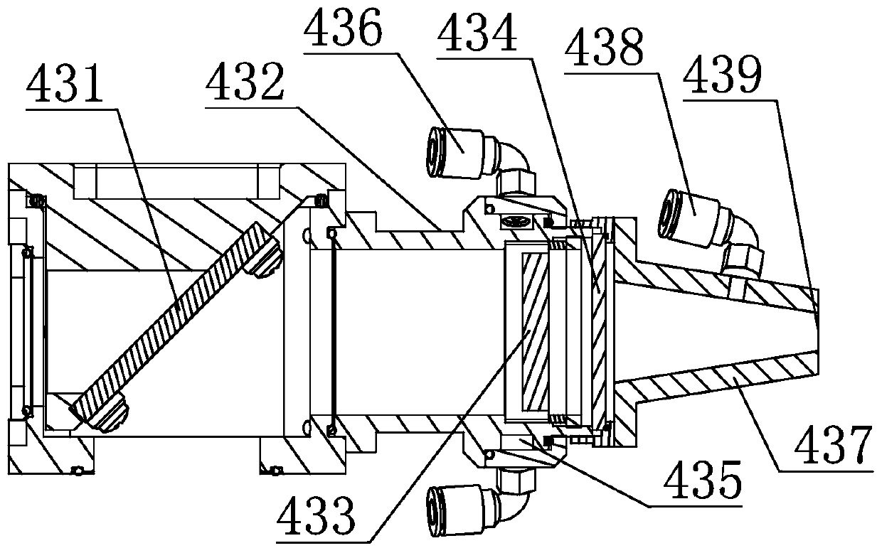
[0024] I...


PUM


Abstract

The invention discloses a pipeline laser welding machine. The pipeline laser welding machine comprises a motor rotary table arranged on a machine base and a clamping and locating device. The clampingand locating device comprises a locating frame and a pipeline clamping mechanism arranged above the center of the electric rotary table. A pipe joint locating device is arranged in the position, belowthe pipeline clamping mechanism, of the electric rotary table. The electric rotary table is provided with a laser welding device. The laser welding device comprises a laser alignment assembly connected with a laser generator, a light path guide assembly and a laser focusing assembly. The laser alignment assembly is fixed to the position, below the center of the electric rotary table, of the machine base. The light path guide assembly is fixedly mounted on the electric rotary table. One end of the light path guide assembly corresponds to the laser alignment assembly, and the other end of the light path guide assembly is connected with the laser focusing assembly. The laser focusing assembly points towards the location between the pipeline clamping mechanism and the pipe joint locating device. Accordingly, the problem that an optical fiber is twined onto equipment easily and fatigue failure is caused is effectively solved, and bending deformation is caused to gas pipe to be welded due to swing can be effectively prevented.

Description

technical field [0001] The invention relates to the technical field of laser welding, in particular to a pipeline laser welding machine. Background technique [0002] When the existing gas pipe laser welding machine welds the gas pipe and the pipe joint, it either realizes the welding of the joint by rotating the gas pipe and the pipe joint, or completes the welding by turning the laser welding device around it; When the gas pipe is welded, due to the long length of the gas pipe, it is easy to swing during the rotation process, which is easy to cause bending deformation, especially the corrugated pipe is easy to break; and the laser welding device is used to weld in circles, and the optical fiber is easy to be wound on the equipment. , and it is also easy to cause fiber damage due to fatigue damage. Therefore, it is necessary to improve and optimize the existing technology. Contents of the invention [0003] The purpose of the present invention is to solve at least one o...

Claims


Application Information

Patent Timeline
IPC IPC(8): B23K26/24B23K26/282B23K26/70
CPCB23K26/24B23K26/282B23K26/70B23K26/702Y02P70/10
Inventor 杨宝燕伍涛
Owner 广东聚金激光技术有限公司
Why Eureka
Try Eureka