Hydraulic balanced motor dynamic sealing device

A sealing device and motor-driven technology, applied in the direction of electromechanical devices, electric components, electrical components, etc., can solve the problems of increasing maintenance costs, leaking motors, wasting time, etc., achieving simple structure, reducing maintenance costs, and simplifying process links. Effect

Inactive Publication Date: 2019-06-07
CSIC NO 710 RES & DEV INST
View PDF4 Cites 5 Cited by
  • Summary
  • Abstract
  • Description
  • Claims
  • Application Information

AI Technical Summary

Problems solved by technology

The advantage of this structure is that standard specification motors can be used, but the disadvantage is that the closed cover and sealing ring of the motor must withstand all external pressure, otherwise any leakage caused by poor sealing will cause damage to the motor
The pressure balanced motor is also sealed with an outer cover, but the cover is filled with non-conductive liquid, and the external pressure is transmitted to the liquid in the cover through the pressure compensation device, and the internal and external pressure difference between the outer cover and the sealing ring is basically balanced, reducing The pressure problem caused by the sealing ring is reduced. At the same time, since the motor is filled with non-conductive liquid, the internal oil will flow out when the sealing ring is replaced, so every time the sealing ring is replaced, the oil needs to be released before it can be sealed. Ring replacement, which not only increases maintenance costs and wastes time

Method used


Image

  • Hydraulic balanced motor dynamic sealing device

Examples


Embodiment Construction

[0014] The present invention will be described in detail below with reference to the accompanying drawings and examples.

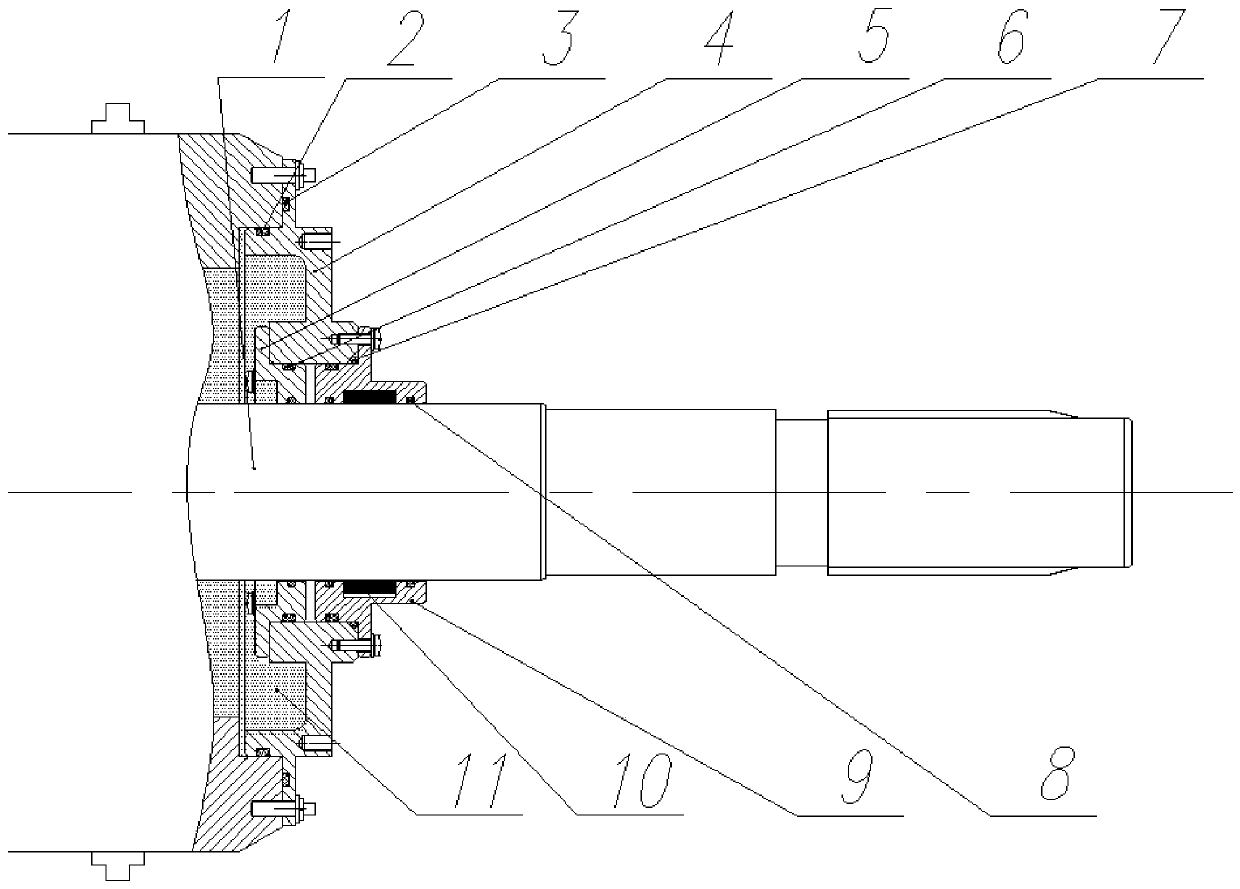
[0015] as attached figure 1 As shown, the present invention provides a dynamic sealing device for an oil pressure balance motor, the device includes an oil pressure balance motor shaft end 1, an O-ring 2, an O-ring 3, a sealing end cover 4, an inner sealing seat 5, a tapered surface O-ring 6, O-ring 7, O-ring 8, outer sealing seat 9, grease 10 and insulating hydraulic oil 11.

[0016] The sealing end cover 4 is fixedly connected to the oil pressure balance motor 1, and the sealing end cover 4 is set on the O-ring by setting an axial O-ring 3 and a radial 45° split mold outer shaft O-ring 2. It needs to be lubricated with 7013 grease, the sealing end cover is made of stainless steel, and the O-ring is made of NBR;

[0017] The inner sealing seat 5 is fixedly connected to the sealing end cover 4, and there are two sealing grooves on the inner sealing seat ...


PUM


Abstract

The invention discloses a hydraulic balanced motor dynamic sealing device. The dynamic sealing device includes a sealing end cap, an inner sealing seat, an outer sealing seat, O-shaped rings, lubricating grease and insulating hydraulic oil; the upper end of the sealing end cap is fixedly connected to a hydraulic balanced motor; the left side on the lower end of the sealing end cap axially and radially limits the inner sealing seat sleeving a motor shaft; the O-shaped rings are installed on the radial contact surfaces of the inner sealing seat and the motor shaft and the sealing end cap; the right side on the lower end of the sealing end cap axially and radially limits the outer sealing seat sleeving the motor shaft; the outer sealing seat is provided with an outer shaft oil chamber; the outer shaft oil chamber is filled with the lubricating grease; the O-shaped rings are installed on the two ends of the outer shaft oil chamber to perform sealing; the O-shaped rings are installed on theradial contact surface of the outer sealing seat and the sealing end cap to perform sealing; and the outer sealing seat is detachably and fixedly connected to the sealing end cap. The dynamic sealingdevice can simplify the technology steps of replacing the sealing rings, so that the maintenance costs of the motor can be reduced.

Description

technical field [0001] The invention relates to a dynamic sealing structure of an underwater oil pressure balance motor, in particular to the technical field of electric dynamic sealing. Background technique [0002] With the continuous exploration of marine resources, underwater robots are more and more widely used, and the dynamic sealing problem of the motor rotating shaft in the propulsion system of underwater robots needs to be solved urgently. Compared with static sealing, the problem of dynamic sealing is more difficult to solve. When the shaft rotates, there will be leakage due to the gap between the shaft and the casing, and the higher the rotating speed of the shaft, the easier it is to generate leakage. [0003] The seal of the rotating shaft of the underwater motor is divided into a pressure-bearing rotary dynamic seal and a pressure-compensated rotary dynamic seal. The enclosed motor uses a motor that is housed in a cover, and a seal ring is added to the output...

Claims


Application Information

Patent Timeline
Patent Type & Authority Applications(China)
IPC IPC(8): H02K5/132H02K5/124
Inventor 彭阿静王力张帆王梦璇李孟捷
Owner CSIC NO 710 RES & DEV INST
Why Eureka
Try Eureka