
Display panel and display device

A display panel and area technology, applied in the direction of identification devices, instruments, electrical components, etc., can solve the problems of screen display failure, OLED materials are prone to breakage, etc., and achieve the effect of maintaining resolution, improving bending effect, and releasing stress.

Active Publication Date: 2019-06-07
WUHAN CHINA STAR OPTOELECTRONICS SEMICON DISPLAY TECH CO LTD
View PDF7 Cites 14 Cited by
  • Summary
  • Abstract
  • Description
  • Claims
  • Application Information

AI Technical Summary

Problems solved by technology

When the flexible OLED screen is impacted by external force, or undergoes repeated bending, curling or laser lift-off (LLO), the inside of the screen is easily affected by stress and strain, especially for the array substrate, where the metal wiring, inorganic layer and OLED materials are prone to cracking, causing screen display failure

Method used


Image

  • Display panel and display device
  • Display panel and display device
  • Display panel and display device

Examples


Embodiment Construction

[0041] The following description of the embodiments refers to the accompanying drawings to illustrate specific embodiments in which the invention may be practiced. The directional terms mentioned in the present invention, such as "up", "down", "front", "back", "left", "right", "top", "bottom", etc., are only for reference to the attached drawings. direction. Therefore, the directional terms used are used to illustrate and understand the present invention, but not to limit the present invention.

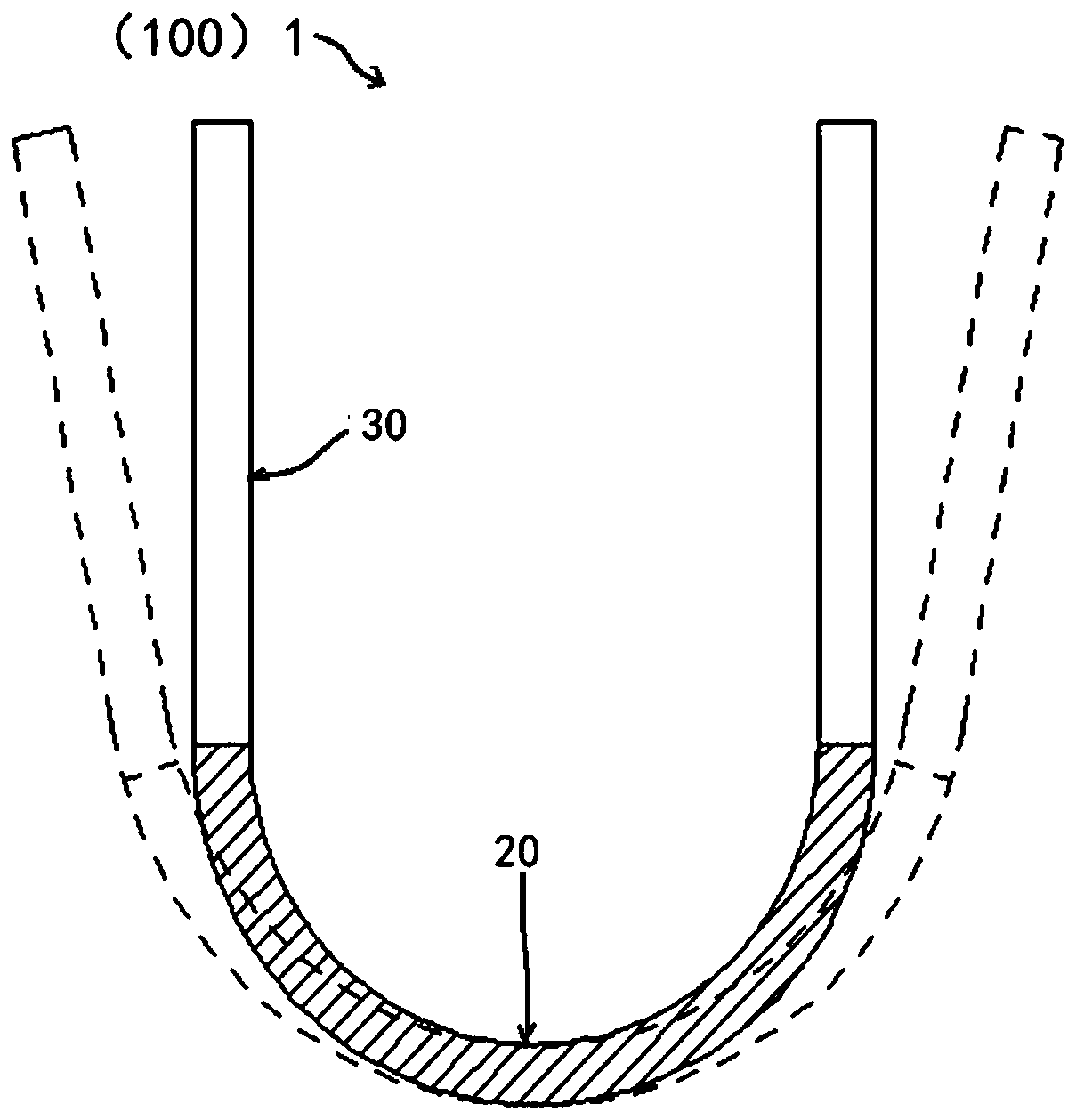
[0042] Such as figure 1 As shown, in one embodiment, the display panel 100 of the present invention has a bending area 20 and at least one non-bending area 30 connected to the bending area 20 . One or two non-bending regions 30 may be provided. In this embodiment, two non-bending regions 30 are provided, which are respectively connected to two sides of the bending region 20 .

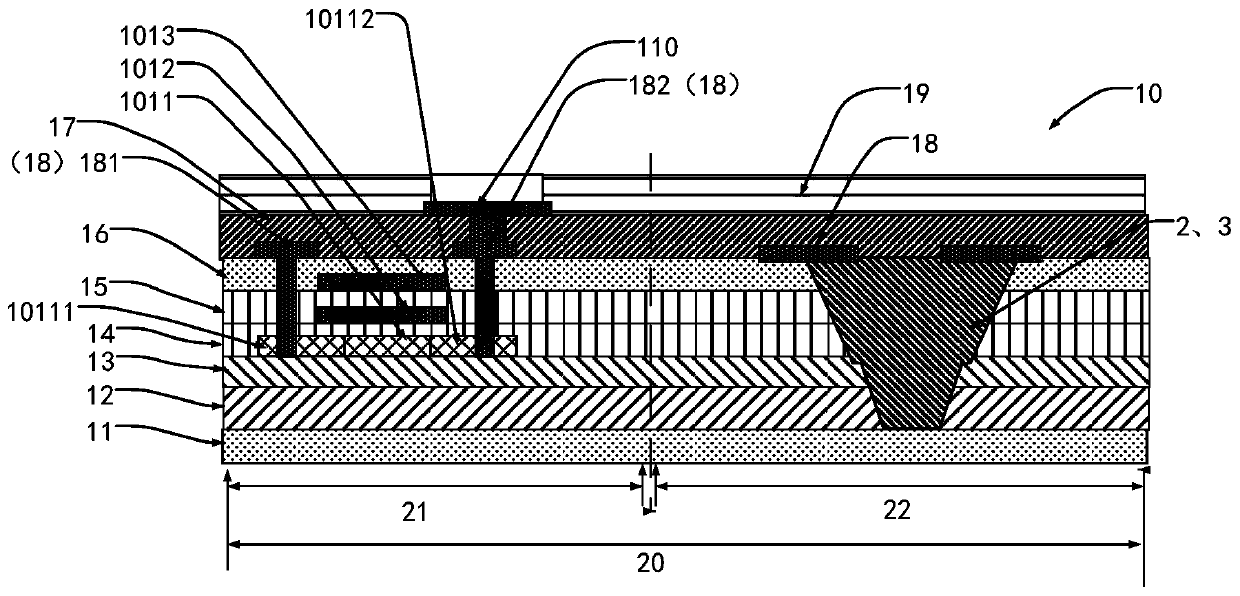
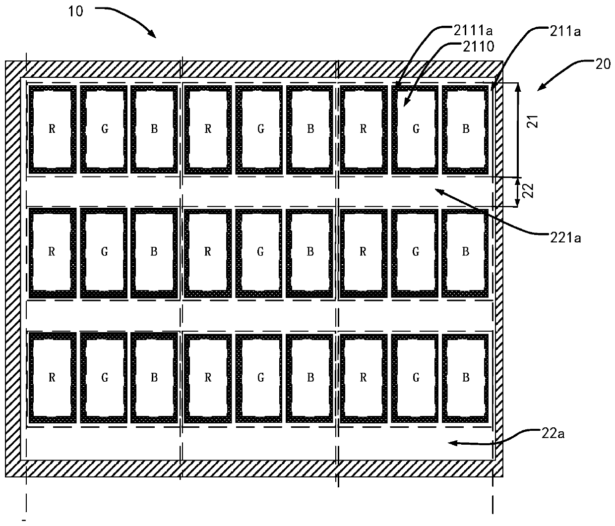
[0043] Such as image 3 , Figure 4 As shown, the display panel 100 of the present invention includes a...


PUM


Abstract

The present invention discloses a display panel. The display panel comprises a bending region and a non-bending region connected with the bending region, and the display panel further comprises an array substrate. The array substrate comprises: a plurality of first pixel regions which are mutually arranged in parallel in multiple lines and arranged in the bending region; a plurality of second pixel regions which are mutually arranged in parallel in multiple lines and arranged in the non-bending region; and a plurality of flexible connection regions configured to connect with adjacent first pixel regions and connect with the first pixel regions and the second pixel regions, wherein each flexible connection region is internally provided with a slot, and each slot is filled with an organic photoresist layer. According to the invention, the slots are arranged in the flexible connection regions of the bending region to form an inorganic layer slot between two adjacent lines of pixel regionsin the bending region to separate from each two lines of pixel regions, and the slots are filled with the organic photoresist layers so as to effectively relieve the stress of each inorganic layer ormetal wiring corresponding in the display panel, especially in the array substrate.

Description

technical field [0001] The invention relates to the field of liquid crystal display, in particular to a display panel and a display device. Background technique [0002] With the development of display technology, centered on OLED display technology, the development and application of a new generation of display technology is in full swing, and has been gradually applied to many fields, such as wearable devices such as smart bracelets, smart watches, VR (Virtual Reality (virtual reality) equipment, mobile phones, e-books and e-newspapers, televisions, personal portable computers, etc. The future of display is OLED, and the future of OLED is flexible display. The current development of "flexible display" technology is just the beginning, and what we have seen is only the tip of the iceberg. With the rapid development of emerging electronic products and the Internet of Things, flexible display technology is clearly the development direction of future electronic products. [...

Claims


Application Information

Patent Timeline
IPC IPC(8): H01L27/32G09F9/30
CPCG09F9/30
Inventor 邬可荣
Owner WUHAN CHINA STAR OPTOELECTRONICS SEMICON DISPLAY TECH CO LTD
Learn More