Supporting plates and supporting device for supporting arch heat exchange tube in heat exchanger as well as mounting method of supporting device

A technology of support device and installation method, which is applied in the direction of heat exchanger shell, assembly machine, heat exchange equipment, etc., can solve the problems of poor tube bundle support rigidity, poor support rigidity, collapse, etc., and achieves strong support structure rigidity and support rigidity. Strong, non-deformable effect

Pending Publication Date: 2019-06-07
DONGFANG BOILER GROUP OF DONGFANG ELECTRIC CORP
View PDF5 Cites 1 Cited by
  • Summary
  • Abstract
  • Description
  • Claims
  • Application Information

AI Technical Summary

Problems solved by technology

[0004] Using the above method, the structure of the tube bundle supporting device is relatively complicated, the assembly is difficult, and there are at least the following three disadvantages:
[0005] (1) It is difficult to locate and align the heat exchange tubes after the tubes are threaded: after the arched heat exchange tubes are penetrated into the tube sheets at both ends, although the positioning of the heat exchange tubes at the positions of the tube sheets at both ends can be ensured, due to the fact that the arched heat exchange tubes are in the The inside of the tube bundle can be rotated in the circumferential direction, and the above-mentioned round steel tie rods are used for support, and a row of horizontal tie rods is passed through. Figure four The structure is equipped with longitudinal tie rods and sleeves, and the bow-shaped heat exchange tubes can only be fixed after the sleeves and tie rods are welded. The manufacturing process is very complicated; when there is no sleeve fixed, the bow-shaped heat exchange tubes can be rotated, and the tube bundle assembly is difficult ;
[0006] (2) Poor anti-deformation of tube bundle tie rod support: In order to ensure that the catalyst falls from the top of the equipment to the bottom to the greatest extent, the tube bundle tie rod support device can only use φ10mm tie rods to form horizontal and vertical tie rod areas to form supports (such as Figure 4 shown), but due to the poor support rigidity of the φ10mm tie rods, the performance of the product cannot be guaranteed; the weight of the tube bundle after passing through the pipe is about 100 tons. Slump, the supporting rigidity of the whole tube bundle is too poor;
[0007] In order to ensure that the support does not deform, it is often necessary to use process support to prevent deformation, that is, to add circumferential support tooling outside the entire tube bundle to prevent deformation; however, this type of process support needs to be removed before the shell and tube bundle are assembled, so the subsequent tube bundle is still Collapse and deformation will occur due to insufficient support structure;

Method used


Image

  • Supporting plates and supporting device for supporting arch heat exchange tube in heat exchanger as well as mounting method of supporting device
  • Supporting plates and supporting device for supporting arch heat exchange tube in heat exchanger as well as mounting method of supporting device
  • Supporting plates and supporting device for supporting arch heat exchange tube in heat exchanger as well as mounting method of supporting device

Examples


Embodiment 1

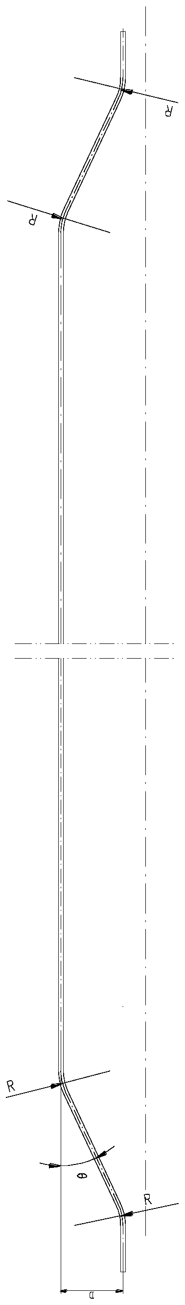
[0041] Such as Figure 7 As shown, this embodiment provides a support plate for supporting arcuate heat exchange tubes in a heat exchanger, the first side 101 of the support plate 10 is provided with a concave first clamping hole 102, and the second side 103 is provided with a concave second clamping hole 104; wherein, the first side 101 and the second side 103 are parallel to each other and are respectively located on opposite sides of the support plate 10, the first clamping hole 102 and the second clamping hole 104 are respectively It is used to fix the top and bottom of the two layers of arcuate heat exchange tubes adjacent up and down in the height direction; and there is also a gap between the first side 101 and the second side 103 of the support plate 10 for the catalyst to pass through. Leak 105.

[0042] The specifications of the first clamping hole 102 and the second clamping hole 104 are consistent, and both are semicircular holes.

[0043] During processing, in o...

Embodiment 2

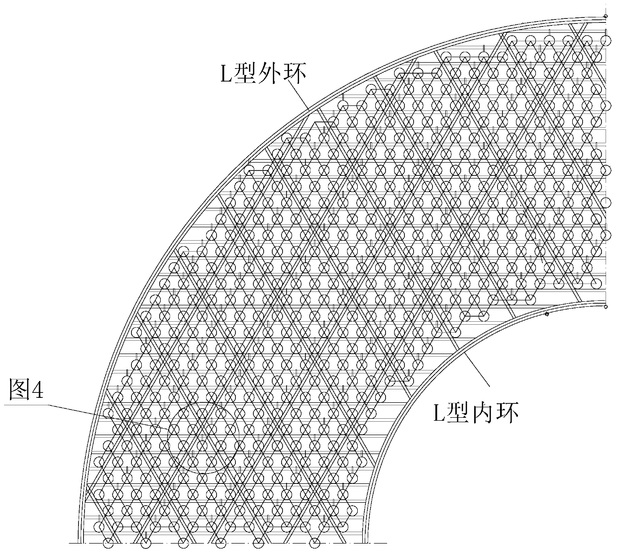
[0048] This embodiment provides a support device for supporting arcuate heat exchange tubes in a heat exchanger. The support device is composed of several support plates 10 described in Embodiment 1. The length L of each support plate 10 depends on its supporting Depending on the position in the device, each support plate 10 is welded to each other to form an annular support device. The outer side of each support plate 10 is fixed to the L-shaped outer ring 201 of the heat exchanger, and the inner side is fixed to the L-shaped inner ring 202 of the heat exchanger. fixed.

[0049] Figure 8 It is a schematic structural view of 1 / 4 part of the supporting device in this embodiment, which is composed of Figure 8 It can be seen that the outer side of the support plate 10 is fixed to the L-shaped outer ring 201 of the heat exchanger, and the inner side is fixed to the L-shaped inner ring 202 of the heat exchanger.

[0050] Figure 9 for Figure 8 A partial enlarged view of Fi...

Embodiment 3

[0052] This embodiment provides a method for installing the support device described in Embodiment 2, which includes the following steps:

[0053] S1. According to the position of each support plate 10 in the support device, number each support plate 10 sequentially according to the order of assembly from bottom to top; Figure 10 As shown, according to the position of the support plate 10, according to the order of assembly from bottom to top, the support plate 10 is numbered from 1, Figure 10 The middle is a schematic diagram of the lower left side 1 / 4 of the support device, the support plates 10 are numbered from 1 to 33, and each label represents a support plate 10;

[0054] S2. Assemble each support plate 10 layer by layer from bottom to top according to the sequence of numbers; during the assembly process, after each support plate 10 is assembled, the corresponding bow-shaped heat exchange tubes are assembled behind the second clamping hole 104 of the support plate 10 ...


PUM


Abstract

The invention discloses supporting plates and a supporting device for supporting arch heat exchange tubes in a heat exchanger as well as a mounting method of the supporting device. The supporting plates provided, first clamping holes which are concave inwards are formed in first side edges of the supporting plates, and a second clamping hole which is concave inwards is formed in a second side edge; the first side edges and the second side edges are parallel to each other and are positioned on two opposite sides of the supporting plates correspondingly; and the first clamping holes and the second clamping holes are used for supporting the tops and the bottoms of the two layers of arch heat exchange tubes which are vertically adjacent in the height direction, and leakage holes allowing a catalyst to penetrate through are further formed between the first side edges and the second side edges of the supporting plates, and the supporting device is composed of the plurality of supporting plates. The inventor designs the supporting plates and the support device formed by the supporting plates, the problems that tube bundle manufacturing, assembling and transporting processes are easy to deform can be solved, the using amount of a process supporting material can be reduced, the manufacturing quality of the tube bundles can be well guaranteed, and meanwhile the manufacturing period and cost can be reduced.

Description

technical field [0001] The invention relates to the field of heat exchangers, in particular to a support structure for arcuate heat exchange tubes. Background technique [0002] In a current large heat exchanger, the heat exchange tube is a bow-shaped heat exchange tube, that is, as figure 1 As shown, the two ends of the heat exchange tube are straight sections, and the middle is also a straight section. The straight section at the two ends is connected to the middle straight section through an oblique section. The connection between the oblique section and the straight section has a rounded corner with a radius of R. The angle between the straight section and the straight section is θ, and the offset distance between the straight section in the middle and the straight section at both ends is D, where the θ value and D value of each heat exchange tube are different, and the whole group of tube bundles The heat exchange tubes are gradual, such as figure 2 shown. [0003] ...

Claims


Application Information

Patent Timeline
Patent Type & Authority Applications(China)
IPC IPC(8): F28F9/013B23P21/00
Inventor 黄军奚旭王彬高洁
Owner DONGFANG BOILER GROUP OF DONGFANG ELECTRIC CORP
Why Eureka
Try Eureka