Double-tube extrusion type layered water stop

An extrusion-type, water-stop technology, applied in wellbore/well components, earthwork drilling, sealing/packing, etc., can solve the problem of limited application scope, reduced development cost, and easy gas leakage of inflatable water-stop devices and other problems, to achieve the effect of good sealing effect, low cost and convenient pumping.

Pending Publication Date: 2019-06-07
河北冀水规划设计有限公司
View PDF0 Cites 0 Cited by
  • Summary
  • Abstract
  • Description
  • Claims
  • Application Information

AI Technical Summary

Problems solved by technology

[0006] The technical problem to be solved in the present invention is to provide a double-pipe extrusion type layered water stop to solve the problem that the traditional layered pumping device can only extract water near the upper and lower parts of the water distribution tank and has a limited scope of application and the inflatable water stop The device is prone to air leakage, so as to meet the water-stop isolation of aquifers at any depth, and is not limited by hole depth and water pressure, so as to increase the convenience and reliability of pumping and reduce development costs

Method used


Image

  • Double-tube extrusion type layered water stop
  • Double-tube extrusion type layered water stop
  • Double-tube extrusion type layered water stop

Examples


Embodiment 1

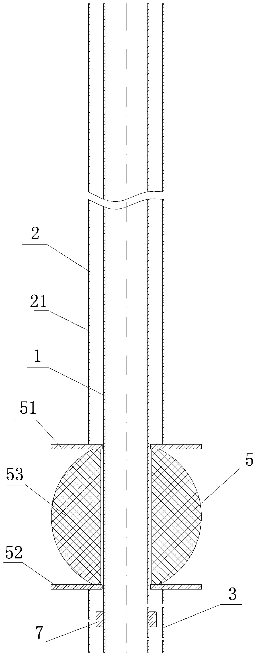
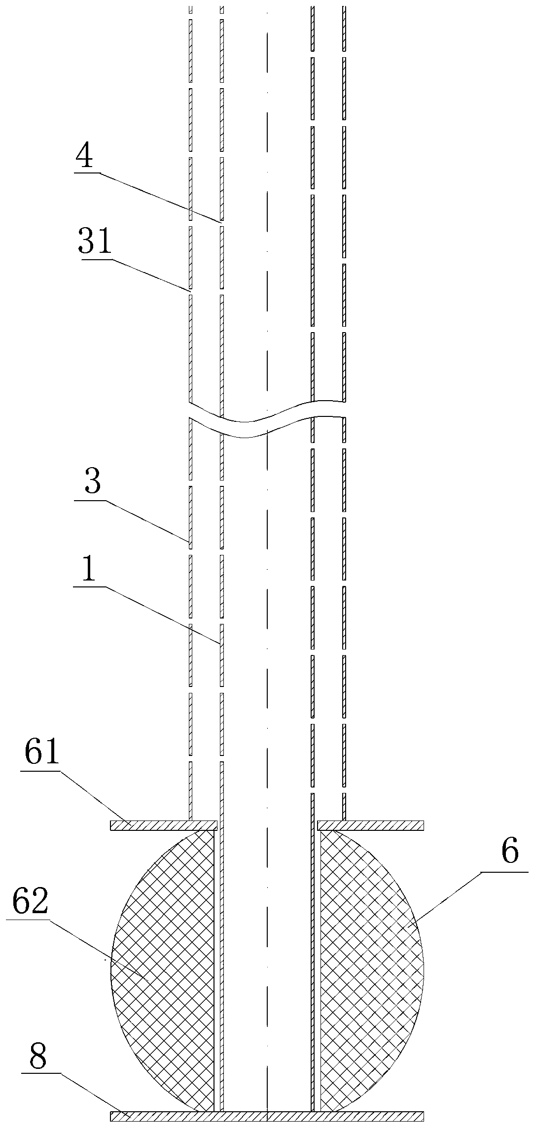
[0033] A double-tube extrusion type layered water stop, combined with Figure 1 to Figure 3 As shown, it includes an inner pipe 1 , an outer pipe 2 , an upper water-stopping mechanism 5 , a lower water-stopping mechanism 6 , a water inlet channel and a bottom baffle 8 .

[0034] The top end of the inner tube 1 is connected with a hoist, and the hoist pulls up the inner tube 1 for positioning. The inner diameter of the inner tube 1 is 28 mm, and the inner tube 1 can be formed by connecting a plurality of segmented tubes of a certain length in sequence, and the segmented tubes are connected by screws. During the actual pumping operation, a water pump is connected to the middle of the inner pipe 1, and the water pump is used to pump the water in the test aquifer into the inner pipe.

[0035] The outer tube 2 is sleeved outside the inner tube 1, the distance between the inner wall of the outer tube 2 and the inner tube is 9mm, and the top end is connected with the hydraulic head,...

Embodiment 2

[0049] On the basis of Example 1, this example is different from Example 1 in that the top deformation blocking structure is set as a white gauze bag containing dry clay a, and the bottom deformation blocking structure is set as a white gauze bag containing dry clay b, dry clay in a knotted white gauze bag a and dry clay in a knotted white gauze bag b, specifically, dry clay in an elastic rubber band knotted white gauze bag. The arrangement of the knotted white gauze bag dry clay a and the knotted white gauze bag dry clay b makes the device more suitable for layered water-stopping of loose aquifers such as sand, pebbles and gravel, thereby increasing the application of the device scope.


PUM


Abstract

The invention discloses a double-tube extrusion type layered water stop which comprises an inner tube and an outer tube, the top end of the inner tube is connected with a winding engine, the outer tube sleeves outside the inner tube and the top end of the outer tube is connected with an oil machine head. The outer tube is sequentially provided with an upper water stop mechanism and a lower water stop mechanism from down to up, the upper water stop mechanism is used for separating an aquifer located at the top of a test aquifer, and the lower water stop mechanism is used for separating an aquifer located at the bottom of the test aquifer. A water inlet channel used for enabling water in the test aquifers to enter the inner tube is arranged between the upper water stop mechanism and the lower water stop mechanism, the inner tube penetrates through the upper water stop mechanism and the lower water stop mechanism and communicates with the water inlet channel, and a bottom partition plateused for sealing and blocking the bottom end of the inner tube is arranged at the bottom end of the inner tube. The double-tube extrusion type layered water stop is free from the limits of hole depthand water pressure, after a hydro-geological borehole is drilled, the requirement of any water stop isolation in a aquifer in any depth is met, additional air inflation equipment is not needed, and leakage of air and water does not exist.

Description

technical field [0001] The invention relates to the technical field of hydrogeological exploration, in particular to a double-tube extrusion type layered water stop. Background technique [0002] Hydrogeological survey is also called "hydrogeological survey". Refers to the hydrogeological investigation and research work carried out to identify the hydrogeological conditions of an area. It aims to grasp the causes, distribution and movement laws of groundwater and surface water. It provides the basis for the rational exploitation and utilization of water resources and the correct design and construction of foundation and piling works. Including two aspects of underground and surface hydrological survey. Groundwater geology survey is mainly to investigate and study the water level change, flow direction, chemical composition, etc. of groundwater in different periods of the year, to find out the burial conditions and erosiveness of groundwater, and to determine the possible ...

Claims


Application Information

Patent Timeline
IPC IPC(8): E21B33/122E21B33/128
Inventor 任卫军刘涛冯亚辉梁崇谦张广扬于清霖赵心广司晓青张友飞秦彩苗刘志利刘健夫朱建勇王利平潘欢庆
Owner 河北冀水规划设计有限公司
Why Eureka
Try Eureka