
Mounting head assembly for stably clamping lens

A technology for installing head and stabilizing equipment, which is applied in the direction of grinding machines, metal processing equipment, grinding/polishing equipment, etc., and can solve problems such as damage, difficult air discharge of cushion pads and limit grooves, and impact on accuracy

Inactive Publication Date: 2019-06-07
中山北方晶华精密光学有限公司
View PDF3 Cites 2 Cited by
  • Summary
  • Abstract
  • Description
  • Claims
  • Application Information

AI Technical Summary

Problems solved by technology

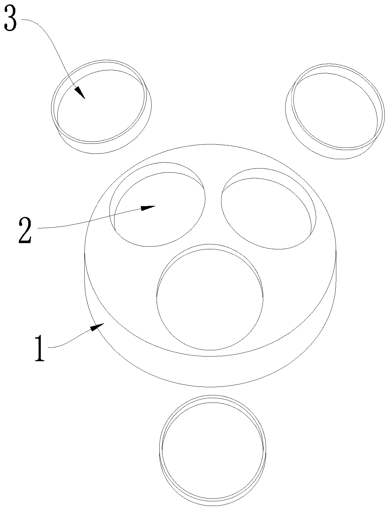
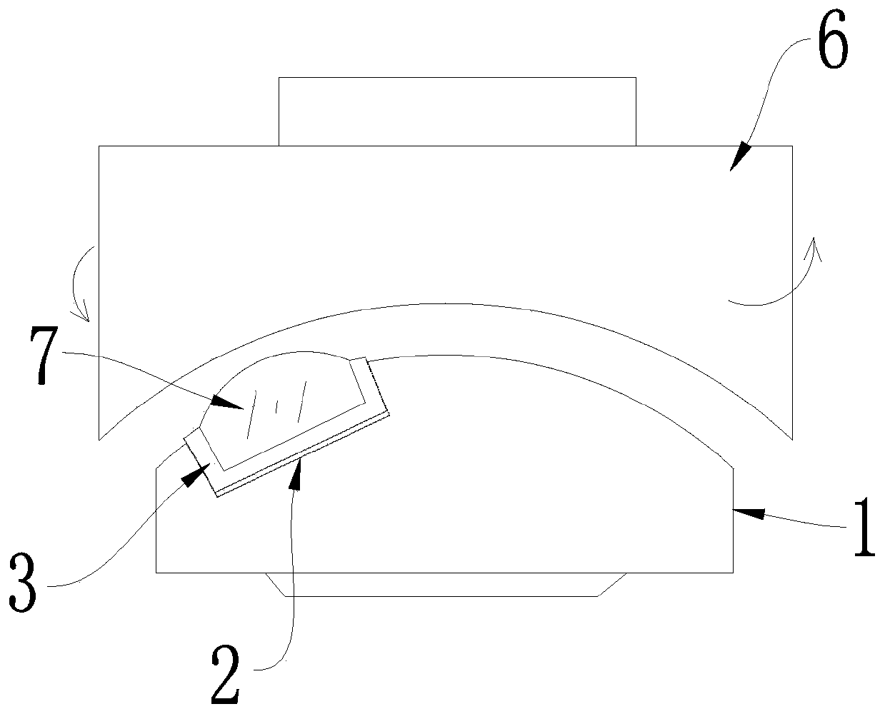
[0002] The existing lens lens radian grinding assembly is composed of a mounting head for placing a fixed lens and a grinding head matched with the mounting head. Figure 1-2 As shown, when the concave surface is polished, the mounting head surface is spherically concave, and the corresponding grinding head surface is spherically convex with the same radian; when the convex surface is polished, the mounting head surface is spherically convex, and the corresponding grinding head surface is spherically concave with the same radian Shape, the surface of the installation head and the surface of the grinding head fit each other; there is a limit groove for placing the lens on the installation head, because the installation head is made of metal, the lens will vibrate during grinding, and it is easy to collide with the installation head to cause damage. To avoid damage to the lens, a cushion made of plastic is usually placed in the limit slot to buffer and absorb shock between the limit slot and the lens. Usually the lens is tightly pressed on the cushion, and the cushion is tightly pressed. in the limit slot
When the lens is polished, it is necessary to continuously inject water to reduce the damage of the lens. The liquid is easy to penetrate through the gap between the cushion pad and the limit groove, and the water pressure is easy to push the cushion pad together with the lens, which affects the precision of lens polishing; On the one hand, due to the tight fit between the cushion pad and the limiting groove, when the cushion pad is pressed into the limiting groove, it is easy to leave air between the cushion pad and the limiting groove and it is difficult to discharge, which eventually causes the lens to protrude slightly and cannot be completely The pressing to the end makes the lens excessively polished and affects the accuracy

Method used


Image

  • Mounting head assembly for stably clamping lens
  • Mounting head assembly for stably clamping lens
  • Mounting head assembly for stably clamping lens

Examples


Embodiment Construction

[0014] The invention provides a mounting head assembly for stably clamping lenses, which is suitable for the field of lens processing. The present invention can be implemented in the following ways:

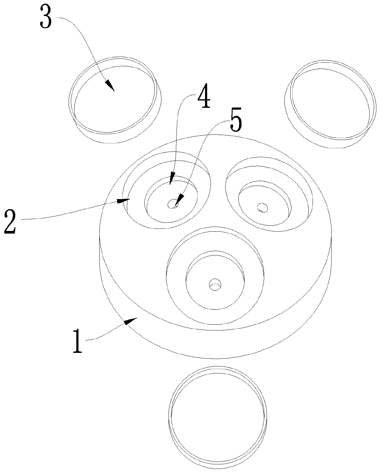
[0015] Such as Figure 3-5 Shown: a mounting head assembly for stably clamping the lens, including a convex spherical mounting head 1, a buffer pad 3 for pressing the lens 7, the groove of the buffer pad 3 is designed based on the shape of the lens 7, which can make the lens It fits seamlessly in the groove of the buffer pad 3. On the grinding surface of the installation head 1, there is a limiting groove 2 for pressing the buffer pad 3. The buffer pad 3 can fit tightly in the limiting groove 2. The bottom surface of the limit groove 2 is provided with an inner groove 4 with a diameter smaller than the limit groove 2. In order to make the bottom surface of the limit groove 2 contact with the buffer pad 3, the buffer pad 3 can be effectively supported to ensure that the grinding ...


PUM


Abstract

The invention relates to the field of lens machining, and provides a mounting head assembly for stably clamping a lens. According to the technical scheme, the mounting head assembly for stably clamping the lens comprises a mounting head (1) and a buffer pad (3) for pressing the lens (7), wherein a limit groove (2) for pressing the buffer pad (3) is arranged on a grinding surface of the mounting head (1); the mounting head assembly for stably clamping a lens is characterized in that an inner groove (4) with a smaller caliber than the caliber of the limiting groove (2) is formed in the bottom surface of the limiting groove (2); and a through hole (5) directly communicating with the outer surface of the grinding surface of the mounting head (1) is formed in the inner groove (4). According tothe technical scheme, the lens (7) is tightly pressed on the mounting head (1), and the grinding precision is improved.

Description

technical field [0001] The invention relates to the field of lens processing, in particular to a mounting head assembly for stably clamping lenses. Background technique [0002] The existing lens lens radian grinding assembly is composed of a mounting head for placing a fixed lens and a grinding head matched with the mounting head. Figure 1-2 As shown, when the concave surface is polished, the mounting head surface is spherically concave, and the corresponding grinding head surface is spherically convex with the same radian; when the convex surface is polished, the mounting head surface is spherically convex, and the corresponding grinding head surface is spherically concave with the same radian Shape, the surface of the installation head and the surface of the grinding head fit each other; there is a limit groove for placing the lens on the installation head, because the installation head is made of metal, the lens will vibrate during grinding, and it is easy to collide wit...

Claims


Application Information

Patent Timeline
IPC IPC(8): B24B13/005B24B13/00
Inventor 袁志峰秦朝锋汤华锡石妹
Owner 中山北方晶华精密光学有限公司
Learn More