A negative feedback automatic gain control circuit and method based on a neural network
An automatic gain control, neural network technology, applied in gain control, neural learning methods, biological neural network models, etc., can solve the problems of inaccurate circuit gain, deviation, etc., to improve error, improve linearity, and high gain control. Effect
- Summary
- Abstract
- Description
- Claims
- Application Information
AI Technical Summary
Problems solved by technology
Method used
Image
Examples
Embodiment 1
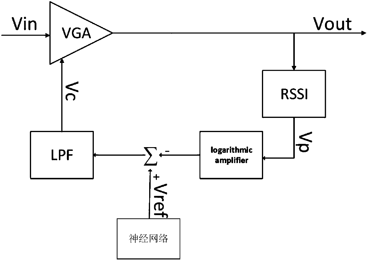
[0091] This embodiment provides a neural network-based negative feedback automatic gain control circuit, including an AGC module and a neural network module;
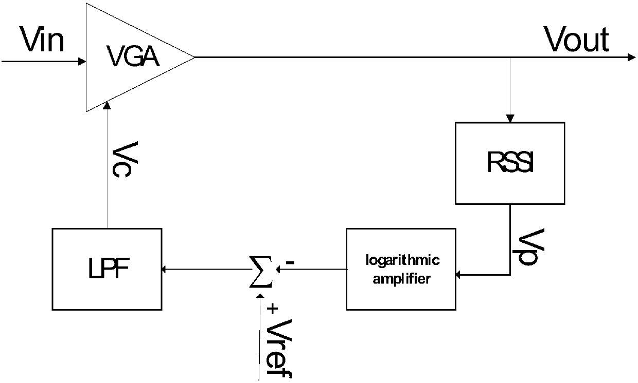
[0092] Further, the AGC module includes a variable gain amplifier VGA, a peak detection RSSI and a low-pass filter LPF. The variable gain amplifier is the core module of the entire AGC, its gain accuracy determines the accuracy of the AGC, and its linearity is an important factor for the linearity of the entire AGC. The peak detector RSSI is used to detect the energy of the output and quantify it, producing a voltage V p . The log amp converts RSSI to the V p Performing logarithmic amplification so that the entire feedback loop has a fixed time constant can also improve the linearity of the circuit. low pass filter for G m _C active filter to filter out the control voltage V c interference signal.
[0093] The neural network generates a reference voltage that can approximate the desired reference voltage with arbi...
Embodiment 2
[0104] On the basis of providing a neural network-based negative feedback automatic gain control circuit as described in Embodiment 1, Figure 6 It is a negative feedback automatic gain control topology diagram based on the LSTM (or RNN) neural network model proposed in this embodiment, consisting of a negative feedback automatic gain control circuit, an LSTM (or RNN) neural network module, and an analog-to-digital conversion It is composed of an ADC, which converts the input analog signal into a digital signal that the neural network can recognize. input signal V in , converted into a digital signal by the ADC, the LSTM (or RNN) neural network module identifies the signal and outputs a high-precision reference voltage according to its network weight value.
Embodiment 3
[0106] On the basis of a kind of negative feedback automatic gain control circuit based on neural network described in embodiment two, Figure 7 It is a kind of negative feedback automatic gain control topology structure diagram based on CNN (or FNN) neural network model proposed by the present embodiment, consisting of a negative feedback automatic gain control circuit, a CNN (or FNN) neural network module, an analog-to-digital conversion ADC and a two-to-one multiplexer register. After the input signal is converted by the ADC, the first register is enabled. When the first register is full, the second register is enabled. The two-choice one multiplex register can be selectively input, and the register has a trigger value. The two-choice A multi-way selection register and the register jointly realize the corresponding voltage (in this application, mainly the input voltage V in and the first control voltage V c ) adjustment of network weights. At the same time, the data stor...
PUM
 Abstract
Description
Claims
Application Information
 - Generate Ideas
- Intellectual Property
- Life Sciences
- Materials
- Tech Scout
- Unparalleled Data Quality
- Higher Quality Content
- 60% Fewer Hallucinations
Browse by: Latest US Patents, China's latest patents, Technical Efficacy Thesaurus, Application Domain, Technology Topic, Popular Technical Reports.
© 2025 PatSnap. All rights reserved.Legal|Privacy policy|Modern Slavery Act Transparency Statement|Sitemap|About US| Contact US: help@patsnap.com


