Efficient multifunctional dust collector

A dust collector, multi-functional technology, applied in the direction of electrostatic effect separation, chemical instruments and methods, dispersed particle filtration, etc., can solve the problems of low dust removal efficiency, dust removal failure, low dust removal efficiency, etc., to increase dust removal efficiency and prolong use The effect of life and work performance improvement

Inactive Publication Date: 2019-06-04
刘艳
View PDF0 Cites 1 Cited by
  • Summary
  • Abstract
  • Description
  • Claims
  • Application Information

AI Technical Summary

Problems solved by technology

[0002] The dust collector is a device that separates dust from the flue gas, called a dust collector or dust removal equipment. The dust removal efficiency of the dust collectors currently on the market is low, especially the bag filter. During use, the gas is cooled below the dew point in the bag room. , especially when the bag filter is used under negative pressure, the following situations are more likely to occur. Because the outer shell often leaks air, the temperature of the gas in the bag room is lower than the dew point, and the filter bag will be damp, so that the dust is not loose, but It is sticky attached to the filter bag, blocking the fabric holes, causing the failure of dust removal, causing the pressure drop of the dust collector to be too large, and it cannot continue to operate.

Method used


Image

  • Efficient multifunctional dust collector
  • Efficient multifunctional dust collector
  • Efficient multifunctional dust collector

Examples


Embodiment Construction

[0014] The following will clearly and completely describe the technical solutions in the embodiments of the present invention with reference to the accompanying drawings in the embodiments of the present invention. Obviously, the described embodiments are only some, not all, embodiments of the present invention.

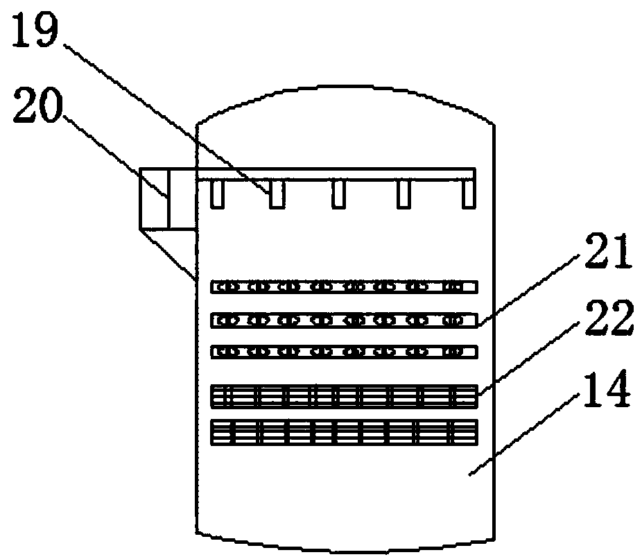
[0015] refer to Figure 1-2 , a high-efficiency multifunctional dust collector, comprising an air injection chamber 6, a filter 8 and a dust removal box 14, the dust removal box 14 is connected to the exhaust chamber 12 through an air inlet pipe 13, and a filter 8 is installed on the upper side of the exhaust chamber 12, and the filter A filter bag 11 is installed on the lower side of the filter 8, an ash storage box 1 is installed on the left side of the filter 8, an electrostatic precipitator 3 is installed on the upper side of the filter 8, and an air intake chamber 2 is installed on the upper side of the electrostatic precipitator 3, and the dust box Ash hopper 1...


PUM


Abstract

The invention discloses an efficient multifunctional dust collector, which comprises an air jet chamber, a filter and a dedusting box. The dedusting box is connected to an exhaust chamber through an air inlet pipe, and the filter is installed on the upper side of the exhaust chamber, a filter bag is installed under the filter, an ash storage bin is installed on the left side of the filter, an electrostatic dust collector is installed on the upper side of the filter, and an air inlet chamber is installed on the electrostatic dust collector, an ash hopper is installed under the dedusting box, and an ash discharge hole is installed under the ash hopper, a bracket is installed under the dedusting box, a pulse valve is installed on the left side of the dedusting box's surface, the air jet chamber is installed on the right side of the pulse valve, an air outlet is mounted on the right side of the air jet chamber, air jet pipes are installed inside the air jet chamber, and a dust collector isinstalled below the air jet pipes. According to the invention, a vibration filter screen is installed inside the dedusting box for vibration of the dust filtered out by the dust collector in the dedusting box, thus accelerating the falling of dust into an deasher, and increasing the dust removal efficiency.

Description

technical field [0001] The invention relates to the technical field of dust removal, in particular to an efficient and multifunctional dust collector. Background technique [0002] The dust collector is a device that separates dust from the flue gas, called a dust collector or dust removal equipment. The dust removal efficiency of the dust collectors currently on the market is low, especially the bag filter. During use, the gas is cooled below the dew point in the bag room. , especially when the bag filter is used under negative pressure, the following situations are more likely to occur. Because the outer shell often leaks air, the temperature of the gas in the bag room is lower than the dew point, and the filter bag will be damp, so that the dust is not loose, but It sticks to the filter bag, blocks the holes of the fabric, causes dust removal failure, makes the pressure drop of the dust collector too large, and cannot continue to operate, and some sticky bags cannot remov...

Claims


Application Information

Patent Timeline
Patent Type & Authority Applications(China)
IPC IPC(8): B01D46/00B01D46/02B01D46/12B01D46/42B03C3/017
Inventor 刘艳
Owner 刘艳
Why Eureka
Try Eureka