
An outdoor dielectrophoresis dust removal equipment

A technology of dielectrophoresis and dust removal equipment, applied in the direction of external electrostatic separator, electrode structure, electrostatic separation, etc., can solve the problems of uneven electric field, failure to achieve the purpose of the invention, etc., and achieve the effect of easy regulation and automation

Inactive Publication Date: 2018-01-26
王冰
View PDF8 Cites 0 Cited by
  • Summary
  • Abstract
  • Description
  • Claims
  • Application Information

AI Technical Summary

Problems solved by technology

In this way, the effect of generating an inhomogeneous electric field in the middle of the electrodes cannot be achieved, so the above-mentioned setting fails to achieve the purpose of the invention

Method used


Image

  • An outdoor dielectrophoresis dust removal equipment
  • An outdoor dielectrophoresis dust removal equipment
  • An outdoor dielectrophoresis dust removal equipment

Examples


Embodiment 1

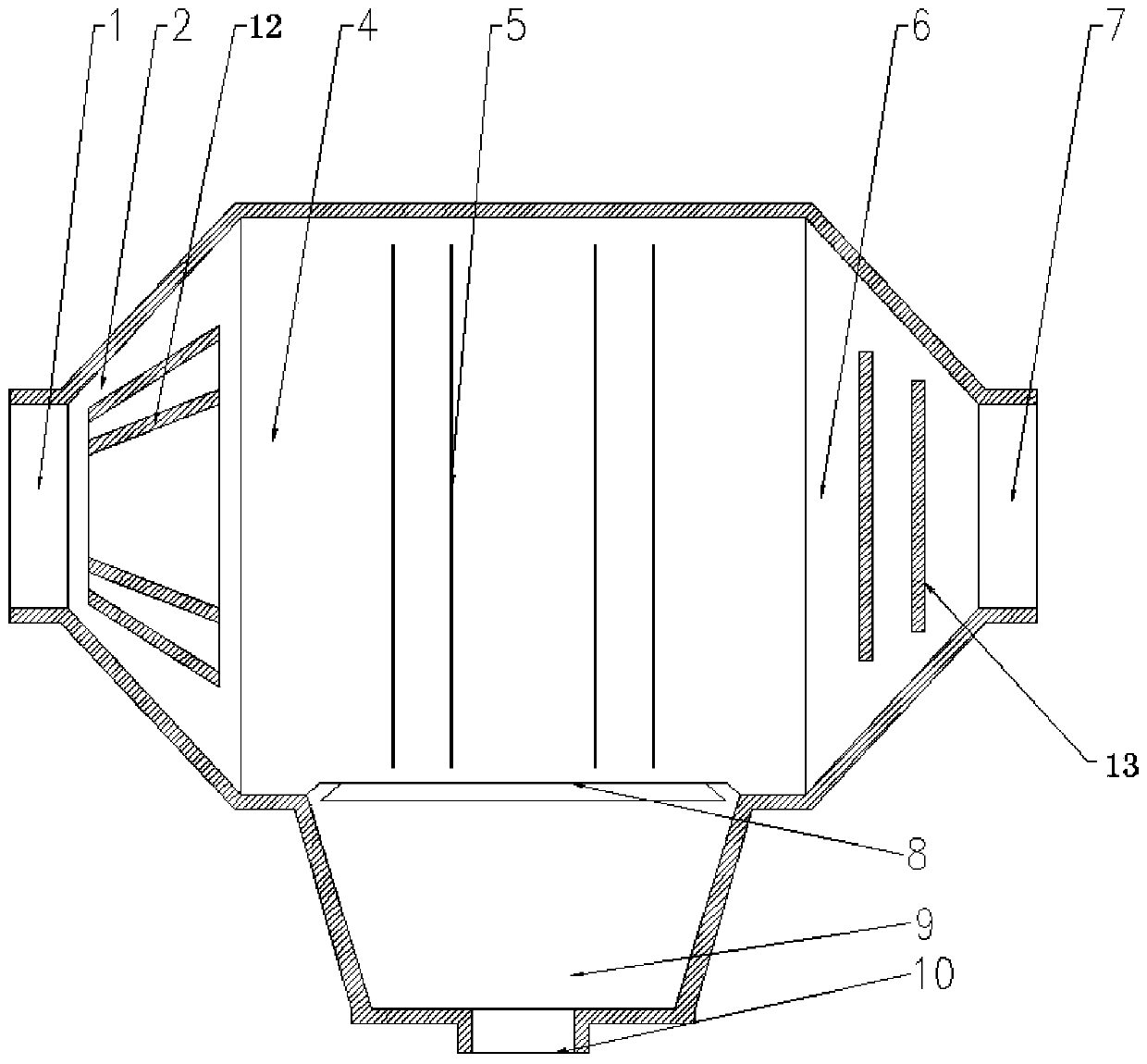
[0058] Such as figure 1 As shown, a kind of outdoor dielectrophoresis dust removal equipment of this embodiment mainly includes a box body 11, an air inlet 1, a mixed flow control room 2, a dielectrophoresis dust removal room 4, a parallel electrode group 5, an outlet smoke box 6, and an air outlet 7 and dust chamber 9. Among them, the box body 11 is a nearly spindle-shaped structure with two ends narrowed and the middle part bulged. One end is provided with an air inlet 1, and the other end is provided with an air outlet 7. It is the dielectrophoresis dust removal chamber 4, and the narrowed part near the air outlet is the outlet smoke box 6. Corresponding to the opening on the bulging part below the dielectrophoretic dust removal chamber 4, a dust collection chamber 9 is connected to the outside of the opening for collecting the dust and particles captured by the parallel electrode groups through the dielectrophoretic force. In this dust collection chamber The bottom of 9 ...

Embodiment 2

[0061] Such as figure 2 As shown, a kind of outdoor dielectrophoretic dedusting equipment of this embodiment differs from that of embodiment 1 in that the mixed flow control chamber 2 is equipped with an air inlet coaxial with the air inlet 1 and gradually expands to the dielectrophoretic dedusting chamber 4. Conical deflector 12. The conical baffles 12 can also be a set of conical baffles coaxially spaced apart. The function of the conical deflector 12 is to evenly distribute the airflow at the air inlet 1, so that the airflow enters the DEP dust removal chamber 4 according to the required speed and direction, so as to avoid the influence of the excessive airflow velocity or direction deviation on the DEP force dust removal effect. In addition, a group of ash collecting baffles 13 arranged in parallel are fixed in the outlet smoke box 6. In this embodiment, they are arranged perpendicular to the direction of the air flow, and the side facing the direction of the air flow i...


PUM


Abstract

The invention relates to outdoor dielectrophoresis dust removing equipment. The middle of a box body of the dust removing equipment is provided with a dust removing chamber. The dust removing chamber of the dust removing equipment is provided with parallel electrode groups. Each parallel electrode group comprises a plurality of parallel dielectrophoresis electrodes. The dielectrophoresis electrodes comprise metal profiles. The cross sections of the metal profiles are in the shapes with protrusions. The protrusions form the ridges of the dielectrophoresis electrodes. According to the outdoor dielectrophoresis dust removing equipment, the structural design is scientific and reasonable; a mixed flow control chamber, the dielectrophoresis dust removing chamber and an outlet smoke box are arranged in the equipment, so that airflow steadily and smoothly gets in and out of the dust removing equipment, and the applicability of the dielectrophoresis dust removing equipment under the outdoor environment is improved; and the parallel electrode groups are adopted, the electrodes of the different electrode groups can be connected to the two ends of an alternating current power source, and a dielectrophoresis effect can be formed in a large-scale range.

Description

technical field [0001] The invention relates to a dust removal device, in particular to an outdoor dielectrophoresis dust removal device. Background technique [0002] At present, environmental protection is becoming more and more important in the world. In order to reduce air pollution and protect the atmospheric environment, as the most important dust removal equipment for controlling atmospheric particulate pollutants, it has a bright prospect for use. Data show that in July 2013, the 10 cities with poor air quality in my country were all in the north, and the Beijing-Tianjin-Hebei region became one of the most polluted regions in the country. The proportion of air quality days in 13 cities in the Beijing-Tianjin-Hebei region ranges from 12.9% to 71%. The average proportion of polluted days is 63.5%, of which the proportion of heavy pollution is 3.7%. This creates conditions for the widespread use of dust removal equipment. Due to the limitation of my country's energy en...

Claims


Application Information

Patent Timeline
Patent Type & Authority Patents(China)
IPC IPC(8): B03C3/04B03C3/12B03C3/34B03C3/36B03C3/45
Inventor 王冰刘伟涛
Owner 王冰
Learn More