a food processor
A technology for food processing machines and machine heads, applied in kitchen utensils, home utensils, applications, etc., can solve problems such as bottom paste, uneven heat transfer, slurry paste pan, etc., and achieve uniform heating, uniform heating of liquid, and mellow taste. Effect
- Summary
- Abstract
- Description
- Claims
- Application Information
AI Technical Summary
Problems solved by technology
Method used
Image

Examples
Embodiment 1
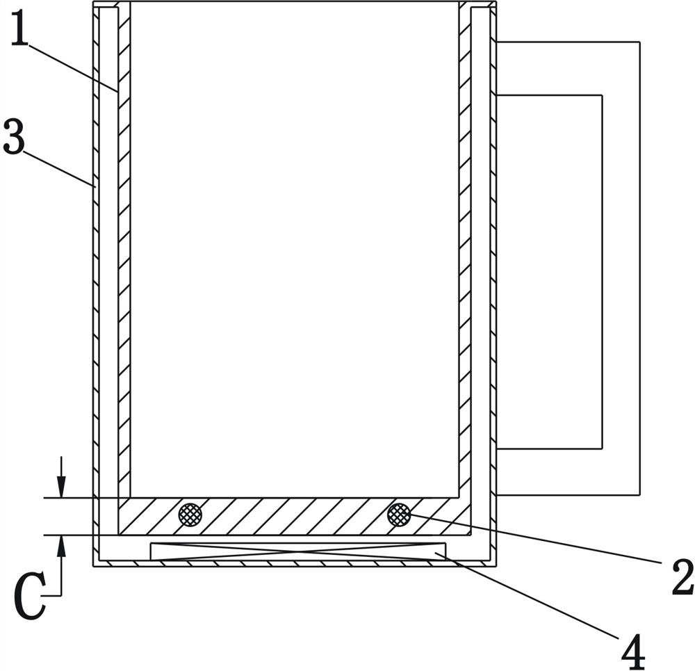
[0036] Such as figure 1 Shown is a schematic structural diagram of the first embodiment of the present invention. A soymilk machine, comprising a machine head (not shown in the figure) and a cup body, the cup body includes a cup body base 1 formed with a liquid holding chamber and a heating body 2 for heating the cavity wall of the cup body base 1, Wherein, the heating body 2 is located at the bottom of the cup base 1 and integrally formed with the bottom cavity wall of the cup base 1 , and the heating body 2 is completely hidden in the bottom cavity wall of the cup base 1 .
[0037] In this embodiment, the cup body further includes a shell 3 , and the cup base 1 is installed in the shell 3 . Located at the bottom of the shell 3, an electromagnetic heating device 4 is provided, and the heating body 2 is an iron-based rod with magnetic induction. When the electromagnetic heating device 4 is energized, the heating body 2 is heated by the induction of the magnetic field.
[00...
Embodiment 2
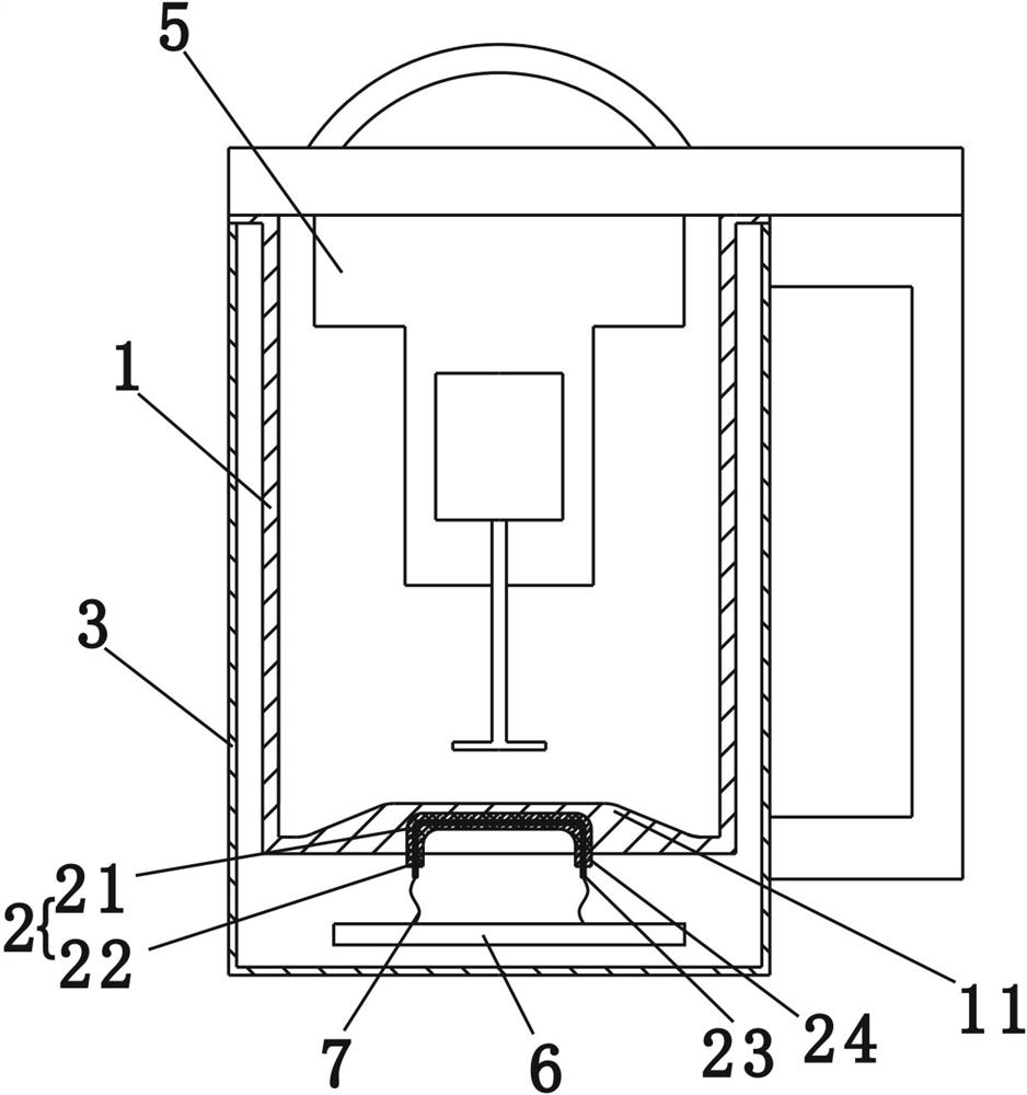
[0045] Such as figure 2 Shown is a schematic structural diagram of the second embodiment of the present invention. This embodiment discloses a soybean milk machine, which includes a machine head 5 and a cup body located below the machine head 5. A motor is arranged inside the machine head, and a rotating shaft driven by the motor penetrates the front end of the machine head and extends into the cup body. at the end of the shaft (not marked in the figure). In this embodiment, the cup has a cup base 1 formed with a liquid-holding cavity, a heating body 2 for heating the cavity wall of the cup base 1, and a housing 3 for installing the cup base 1, wherein the heating The body 2 is located at the bottom of the cup base 1 and integrally formed with the bottom cavity wall of the cup base 1 .
[0046] In this embodiment, the bottom of the cup base 1 has an upwardly protruding protruding portion 11, and the heating body 2 includes a heating portion 21 and a connecting portion 22. T...
Embodiment 3
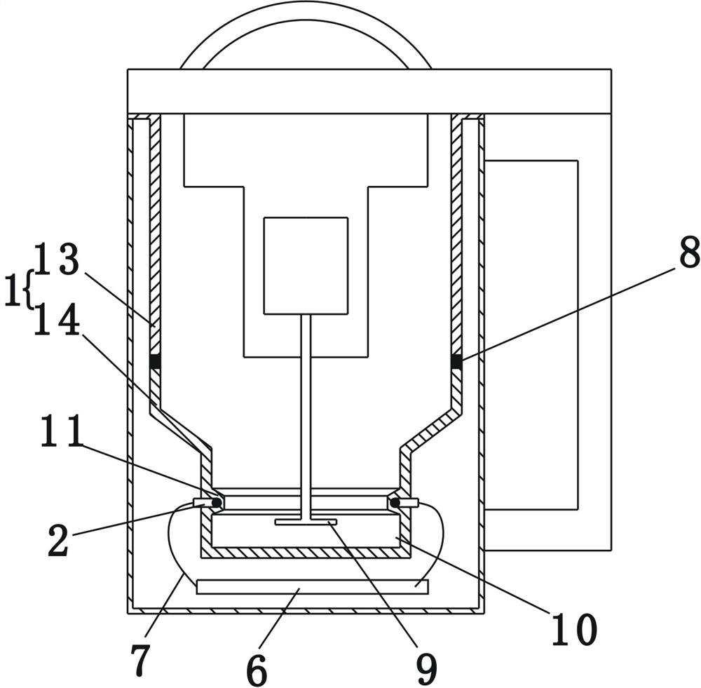
[0051] Such as image 3 Shown is a schematic structural view of the third embodiment of the present invention. The difference between this embodiment and the second embodiment is that: in this embodiment, the cup base 1 includes an upper cup body 13 and a lower cup body 14, and the upper cup body 13 and the lower cup body 14 are sealed and connected by a sealing member 8, The bottom of the lower cup body 14 shrinks inwardly to form a crushing chamber 10 , and the crushing blades 9 are connected by a rotating shaft and extend into the crushing chamber 10 .
[0052] Wherein, the cavity wall of the crushing chamber 10 is provided with an inwardly protruding protruding portion 11, and the protruding portion 11 is ring-shaped, and the heating body 2 is also ring-shaped, wherein the middle part of the heating body 2 is hidden in the protruding portion 11 Inside, the lead-out end of the heating body 2 protrudes from the wall of the crushing chamber 10 , and the lead-out end is elect...
PUM
 Abstract
Description
Claims
Application Information
 - R&D
- Intellectual Property
- Life Sciences
- Materials
- Tech Scout
- Unparalleled Data Quality
- Higher Quality Content
- 60% Fewer Hallucinations
Browse by: Latest US Patents, China's latest patents, Technical Efficacy Thesaurus, Application Domain, Technology Topic, Popular Technical Reports.
© 2025 PatSnap. All rights reserved.Legal|Privacy policy|Modern Slavery Act Transparency Statement|Sitemap|About US| Contact US: help@patsnap.com