Geometric parameter automatic adjusting mechanism and control method thereof

An automatic adjustment and geometric parameter technology, applied in the field of track measurement, can solve the problems of unstable force, easy tilting or flipping of the vertical adjustment mechanism, etc., and achieve the effect of stable screw transmission

Inactive Publication Date: 2019-05-31
成都源视科技有限公司
View PDF4 Cites 0 Cited by
  • Summary
  • Abstract
  • Description
  • Claims
  • Application Information

AI Technical Summary

Problems solved by technology

[0002] The transmission part of the traditional geometric parameter automatic adjustment mechanism is set up by the horizontal adjustment mechanism and the vertical adjustment mechanism, driven by the servo motor, and adjusted through the transmission of the worm gear and the sliding screw, that is, converting the rotational motion into a linear reciprocating motion. During the movement, due to the vertical There is a transmission screw on the adjustment mechanism, which will easily cause unstable force, and at the same time, the vertical adjustment mechanism will easily tilt or turn over during the movement process.

Method used


Image

  • Geometric parameter automatic adjusting mechanism and control method thereof
  • Geometric parameter automatic adjusting mechanism and control method thereof
  • Geometric parameter automatic adjusting mechanism and control method thereof

Examples


Embodiment 1

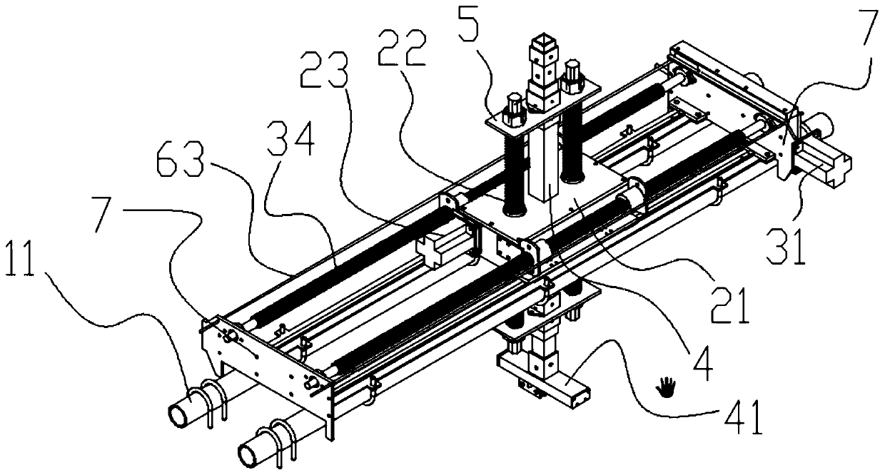
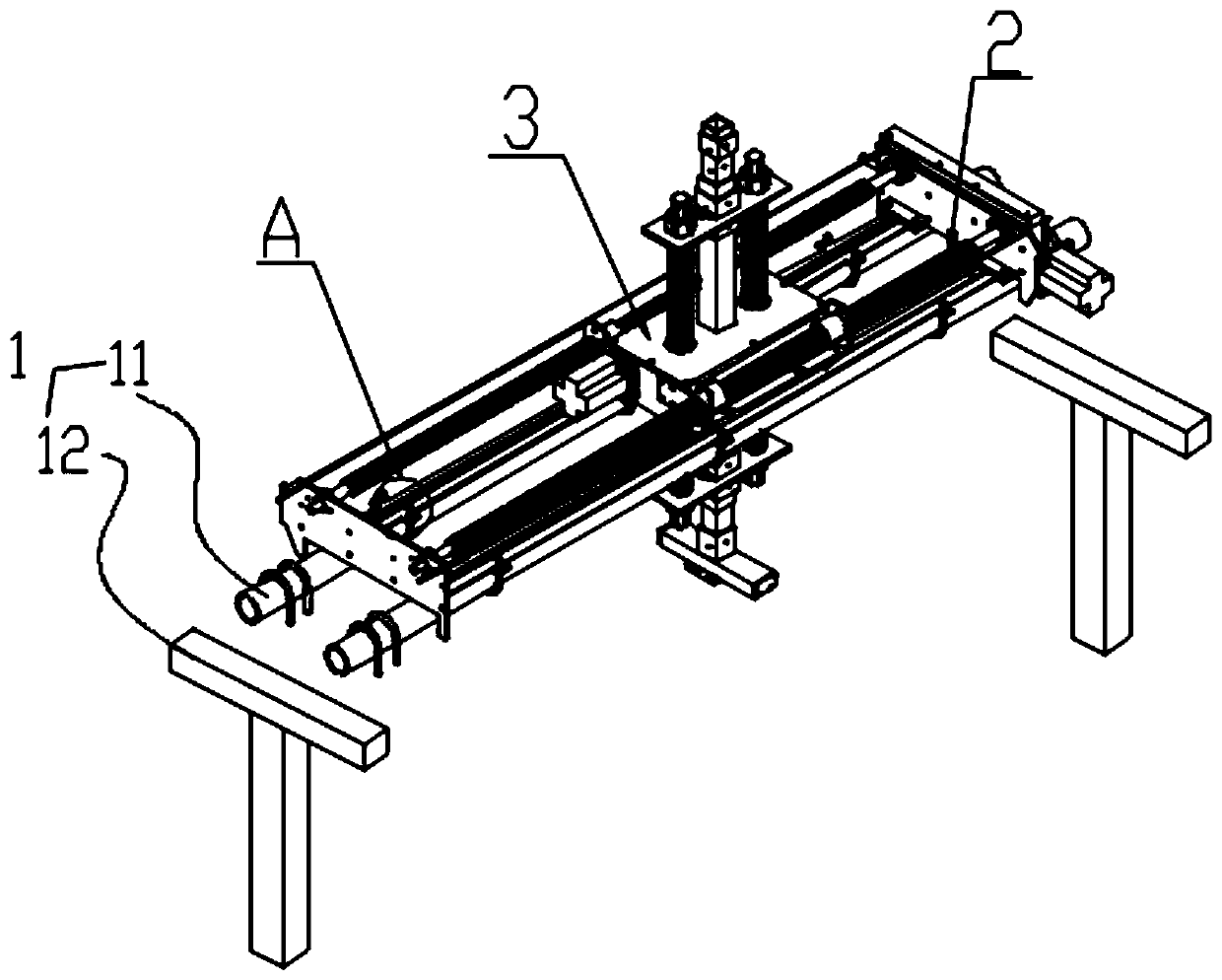
[0043] Such as Figure 1-6As shown, a geometric parameter automatic adjustment mechanism includes a load-bearing platform 1 and a vertical adjustment mechanism 2 and a horizontal adjustment mechanism 3 arranged on the load-bearing platform 1. The load-bearing platform 1 includes an installation steel pipe 11 and is provided with two The two ends of the installation steel pipe 11 are provided with mounting parts 7 for installing the horizontal adjustment mechanism 3; the horizontal adjustment mechanism 3 includes a first motor 31, a first turbine 32, a first worm 33 and multiple A horizontal transmission screw 34, the first turbine 32 and the first worm 33 are arranged on one side of one of the mounting parts 7, the horizontal transmission screw 34 is arranged between the mounting parts 7, and the horizontal transmission screw 34 Connect the first turbine 32, the output shaft of the first motor 31 is connected to the first worm 33; the vertical adjustment mechanism 2 includes a...

Embodiment 2

[0046] Such as Figure 1-6 As shown, in this embodiment, on the basis of Embodiment 1, the automatic adjustment mechanism also includes a connecting steel pipe 4, the two ends of the vertical transmission screw 22 are provided with a fixing frame 5, and the fixing frame 5 is connected to the base 21 is provided with a through hole for the connecting steel pipe 4 to pass through, the axis of the connecting steel pipe 4 is parallel to the axis of the vertical transmission screw 22 , and the bottom of the connecting steel pipe 4 is provided with a wire clamp mechanism 41 .

[0047] The connecting steel pipe 4 is connected with the vertical transmission screw rod 22 by the fixed frame 5, and the through hole for the connecting steel pipe 4 to pass is provided on the base 21 simultaneously. Make whole vertical adjustment mechanism 2 keep steady in the process.

Embodiment 3

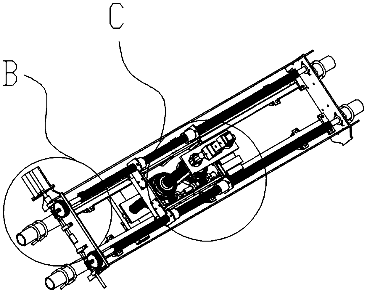
[0049] Such as Figure 1-6 As shown, this embodiment is based on Embodiment 1, and both the horizontal conveying screw 34 and the vertical conveying screw 22 are two. The horizontal conveying screw 34 and the vertical conveying screw 22 are arranged in two in order to prevent tilting or overturning during the moving process.


PUM


Abstract

The invention discloses a geometric parameter automatic adjusting mechanism. The geometric parameter automatic adjusting mechanism comprises a bearing platform, and a vertical adjusting mechanism anda horizontal adjusting mechanism which are arranged on the bearing platform, the bearing platform comprises a mounting steel pipe and support rod pieces installed at two ends of the mounting steel pipe, and the two ends of the mounting steel pipe are provided with mounting pieces configured to install the horizontal adjusting mechanism. The present invention further discloses a control method of ageometric parameter automatic adjusting mechanism. There are a plurality of horizontal transmission screw rods and a plurality of vertical transmission screw rods so that tilting or turning is avoided in the adjusting process, and the thread transmission is more stable.

Description

technical field [0001] The invention relates to the technical field of track measurement, in particular to a geometric parameter automatic adjustment mechanism and a control method. Background technique [0002] The transmission part of the traditional geometric parameter automatic adjustment mechanism is set up by the horizontal adjustment mechanism and the vertical adjustment mechanism, driven by the servo motor, and adjusted through the transmission of the worm gear and the sliding screw, that is, converting the rotational motion into a linear reciprocating motion. During the movement, due to the vertical The adjustment mechanism is provided with a transmission screw, which may easily cause unstable force, and at the same time cause the vertical adjustment mechanism to easily tilt or turn over during the movement process. Contents of the invention [0003] In order to solve the problems existing in the prior art, the object of the present invention is to provide a geome...

Claims


Application Information

Patent Timeline
Patent Type & Authority Applications(China)
IPC IPC(8): G01D11/30G01D21/02G08C17/02
Inventor 杨燕
Owner 成都源视科技有限公司
Why Eureka
Try Eureka