Speed changing device, gear-shifting control method, electric car driving system and electric car

A technology of a speed change device and passive element, which is applied in the field of transmission system, can solve the problems of power interruption, the inability to achieve both the power performance and the power consumption economy of electric vehicles, and the inability to give full play to the power performance and economy of the whole vehicle at the same time.

Active Publication Date: 2019-05-31
NIO CO LTD +1
View PDF7 Cites 7 Cited by
  • Summary
  • Abstract
  • Description
  • Claims
  • Application Information

AI Technical Summary

Problems solved by technology

[0002] At present, electric passenger vehicles generally use a drive motor coupled with a single speed ratio reducer to output power to the wheels, but a single speed ratio reducer cannot give full play to the power and economy of the vehicle at the same time
In the case of a certain drive motor, in order to meet the power requirements, the speed ratio of the reducer needs to be greater than a certain value, and in order to meet the maximum speed or to obtain the best power economy etc.), the speed ratio of the reducer needs to be lower than a certain value, so the use of a single speed ratio reducer usually cannot achieve both the power performance and power consumption economy of electric vehicles
At present, a small number of electric vehicles have adopted two-speed transmissions to balance the power and energy consumption of electric vehicles. If a synchronizer or other mechanical shifting components are used to realize the shifting process during the shifting process of the transmission, there will be The problem of power interruption during the shifting process; and the use of wet clutches as shifting elements has the problem of high energy loss caused by maintaining the high pressure of the oil pump during the gear holding period

Method used


Image

  • Speed changing device, gear-shifting control method, electric car driving system and electric car
  • Speed changing device, gear-shifting control method, electric car driving system and electric car
  • Speed changing device, gear-shifting control method, electric car driving system and electric car

Examples


Embodiment Construction

[0033] The following is a description of exemplary embodiments of the application, examples of which are illustrated in the accompanying drawings.

[0034] For purposes of brevity and illustration, the principles of the application are described herein primarily with reference to exemplary embodiments thereof. However, those skilled in the art will readily recognize that the same principles are equally applicable to and can be implemented in all types of transmissions and shift control methods without departing from this patent application. true spirit and scope. Moreover, in the following description, reference is made to the accompanying drawings, which illustrate certain exemplary embodiments. Electrical, mechanical, logical and structural changes may be made to these embodiments without departing from the spirit and scope of the application. Furthermore, although a feature of the present application is disclosed in connection with only one of several implementations / embo...


PUM


Abstract

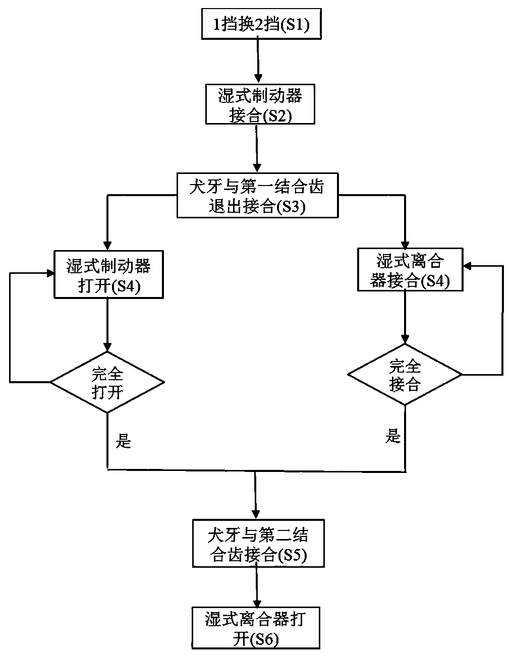
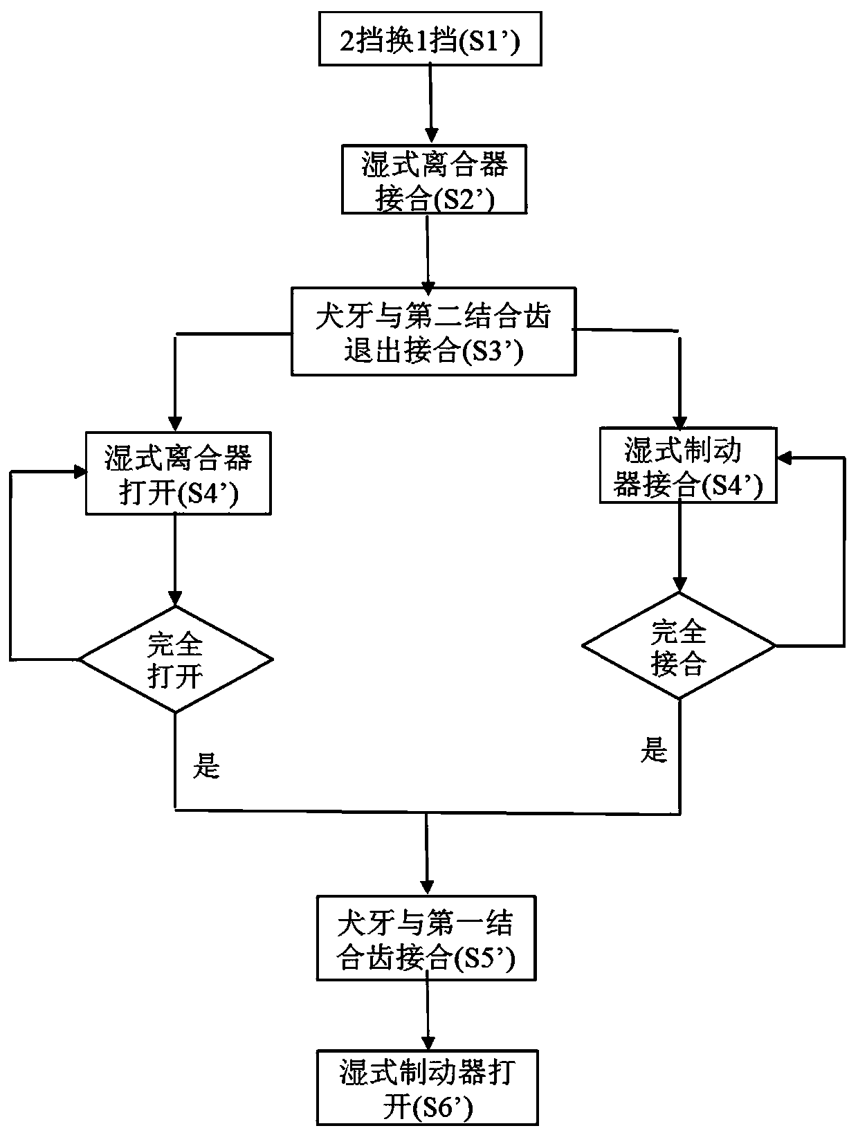
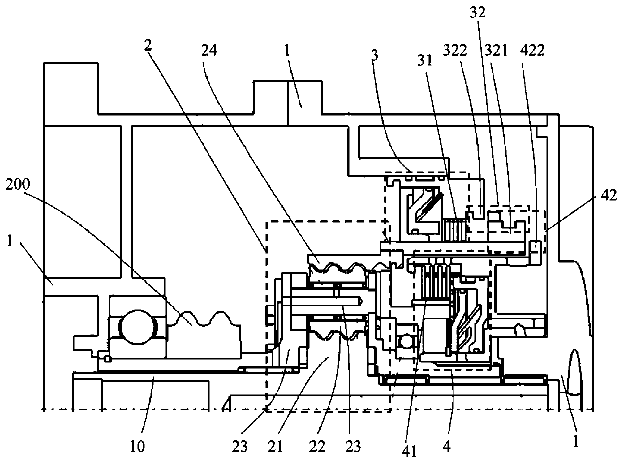
The invention relates to a speed changing device used for a drive system. The speed changing device comprises a planetary gear mechanism including a sun gear and a gear ring, at least one planetary gear meshed between the sun gear and the gear ring, a planet carrier and a gear-shifting mechanism; the sun gear, the planet carrier and the gear ring are configured to be an active component, a drivencomponent and a passive component correspondingly, wherein the active component is driven by the drive system, and the driven component is used as output of the speed changing device; and the gear-shifting mechanism includes a first gear-shifting assembly and a second gear-shifting assembly, the first gear-shifting assembly and the second gear-shifting assembly each include a sliding friction engagement element and a mechanical engagement element which cooperate with each other, each sliding friction engagement element is configured to execute the gear shifting process and achieve release after the gear shifting process is ended, and each mechanical engagement element is used for keeping the gear state after the gear-shifting process is completed and achieving release in the gear-shiftingprocess; and in the engaged state of the first gear-shifting assembly, the passive component is locked, and in the engaged state of the second gear-shifting assembly, the passive component and the driven component are engaged.

Description

technical field [0001] The present application relates to a transmission system, in particular, to a speed change device of a drive system and a shift control method. In addition, the present application also relates to an electric vehicle drive system and an electric vehicle. Background technique [0002] At present, electric passenger vehicles generally use a drive motor coupled with a single speed ratio reducer to output power to the wheels, but a single speed ratio reducer cannot give full play to the power and economy of the vehicle at the same time. In the case of a certain drive motor, in order to meet the power requirements, the speed ratio of the reducer needs to be greater than a certain value, and in order to meet the maximum speed or to obtain the best power economy etc.), the speed ratio of the reducer needs to be lower than a certain value, so the use of a single speed ratio reducer usually cannot have both the power performance and the economy of power consum...

Claims


Application Information

Patent Timeline
IPC IPC(8): F16H61/04
Inventor 刘怀远张铃陈远峰
Owner NIO CO LTD
Why Eureka
Try Eureka