Safety protection device with pre-deceleration function for buffering elevator out-of-control falling

A safety protection device, elevator control technology, applied in transportation and packaging, compressed gas generation, offensive equipment, etc., can solve the problems of passenger impact injury, passenger disability, death, etc., to improve accuracy, reduce casualties, Damage reduction effect

Inactive Publication Date: 2019-05-31
朱爱民
View PDF8 Cites 3 Cited by
  • Summary
  • Abstract
  • Description
  • Claims
  • Application Information

AI Technical Summary

Problems solved by technology

Moreover, according to the development history of elevators in our country, elevators in our country are gradually entering a critical period of general aging, and the safety of elevators has become increasingly prominent. However, elevators that are currently in service or will be put into use across the country generally lack safety protection devices.
[0004] In the prior art, buffers are provided in the bottom pit of the elevator shaft to buffer the huge impact force when the car falls. Although this structure can reduce the degree of accident damage, the degree of accident damage reduction is limited, especially in high-speed elevators. In the accident of squatting at the bottom, this kind of structure is even more insignificant to the reduction of accident casualties. The existing rigid elevator buffer base is not conducive to reducing the harm of the elevator squatting at the bottom of the accident, and cannot meet the needs of elevator operation safety. For this reason, related technical fields Technical staff have improved this. For example, the Chinese patent application number is CN201620645532.5, which proposes a new type of elevator buffer base, including a buffer mounting plate and a base mounting plate. There is also a The middle plate and the base mounting plate are welded with a spring limit post, the spring limit post is covered with a buffer spring, and the middle plate is provided with a through hole, and the spring limit post passes through the through hole and cooperates with the nut to secure the base mounting plate. It is fixedly connected with the middle plate, and the two ends of the buffer spring are respectively pressed against the base mounting plate and the middle plate. Although the present invention can meet the characteristics of reducing the damage to passengers caused by the elevator squatting accident through two-stage buffering and improving the safety performance of the elevator , but the technical solution in the application document still has deficiencies. For example, the buffer and buffer spring of the device are stacked, and both are energy-storage buffer devices. It is still possible to cause impact damage to passengers in the elevator when falling faster
[0006] In the above scheme, although the inside and outside of the car are buffered simultaneously to increase the buffering force, it is too rash to rely solely on passengers' self-rescue to ensure life safety. On the one hand, passengers are prone to panic when the elevator loses control and falls, and it is difficult for the brain to make a calm judgment and self-rescue On the other hand, when the elevator falls out of control, the passengers are in a state of high-speed descent, close to free fall, and it is difficult to use their own strength to complete self-rescue. At this time, relying on the second buffer device outside the car is far from achieving effective buffering. The car is still easy to cause disability or even death to the passengers in the car

Method used


Image

  • Safety protection device with pre-deceleration function for buffering elevator out-of-control falling
  • Safety protection device with pre-deceleration function for buffering elevator out-of-control falling
  • Safety protection device with pre-deceleration function for buffering elevator out-of-control falling

Examples


Embodiment 1

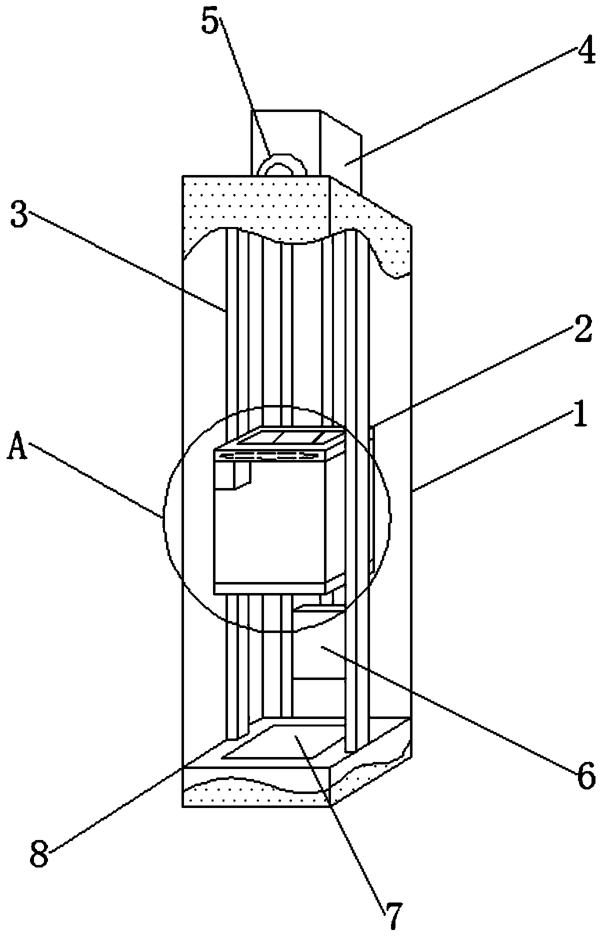
[0047] see figure 1 , a buffer safety protection device for an elevator runaway fall with a pre-deceleration function, comprising an elevator shaft 1, an elevator car 2, guide rails 3, an elevator control cabinet 4, a traction machine 5, a counterweight 6 and a buffer 7, the prior art It is obviously far from enough to only rely on the buffer 7 to buffer the impact force of the elevator car 2 descending at a high speed, which will cause casualties easily after the elevator accident takes place.

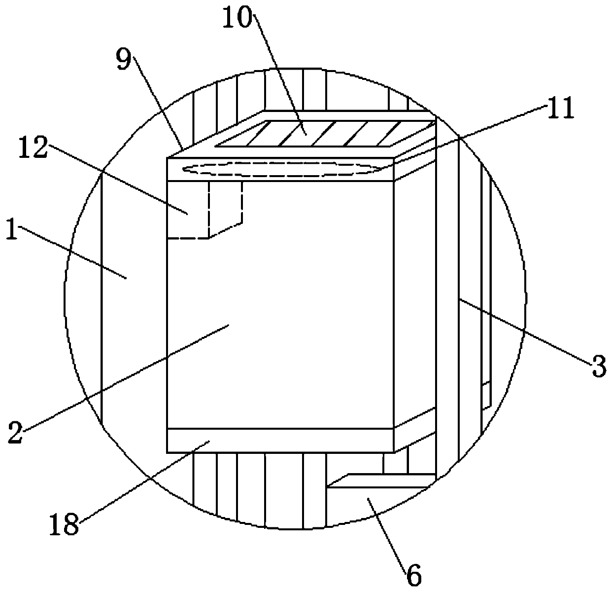
[0048] see Figure 1-2 , the top of the elevator car 2 is fixedly connected with the auxiliary control cabinet 12, which is separated from the elevator control cabinet 4 to realize independent operation and independent control, so as to prevent the elevator car 2 from being out of control after the elevator control cabinet 4 fails, and the auxiliary control cabinet 12 cannot be normal. Operation, useless, the sub-control cabinet 12 of independent operation can still run independently...


PUM

PropertyMeasurementUnit
particle sizeaaaaaaaaaa
diameteraaaaaaaaaa

Abstract

The invention discloses a safety protection device with a pre-deceleration function for buffering the elevator out-of-control falling, and belongs to the technical field of elevator safety. Accordingto the safety protection device with the pre-deceleration function for buffering the elevator out-of-control falling, when an elevator is suddenly failed so as to cause the lift car out-of-control falling, the opening and the running of the pre-deceleration mechanism are timely ensured through a starting mechanism, and the lift car is pre-decelerated for the first time by utilizing air resistanceduring the lift car falling process; through the cooperation of an annular electromagnet arranged on the bottom part of the lift car and a fixed electromagnet arranged on a buffer on a shaft bottom ofthe elevator, the lift car is pre-decelerated for the second time by utilizing a giant magnetic field force; meanwhile, a first-time pre-deceleration unit is promoted and corrected according to a magnetic field distribution characteristic of the annular electromagnet; and finally, through the combined action of an energy absorption layer and the buffer on the bottom part of the annular electromagnet, a giant impact force generated during the lift car falling is absorbed and stopped, so that the harm on passengers in the lift car is remarkably reduced, and the personal casualty is reduced.

Description

technical field [0001] The invention relates to the technical field of elevator safety, more specifically, to an elevator runaway fall buffer safety protection device with a pre-deceleration function. Background technique [0002] Elevator refers to the permanent transportation equipment that serves several specific floors in the building, and its car runs on at least two rigid rails perpendicular to the horizontal plane or with an inclination angle of less than 15° from the plumb line. Running continuously on the crawler belt, commonly known as escalators or moving walks, serving fixed lifting equipment for specified floors, vertical lifts have a car that runs between at least two vertical or rigid guide rails with an inclination angle of less than 15°, The size and structural form of the car are convenient for passengers to enter and exit or load and unload goods. It is customary to use elevators as a general term for vertical transportation in buildings regardless of thei...

Claims


Application Information

Patent Timeline
Patent Type & Authority Applications(China)
IPC IPC(8): B66B5/28B66B5/00C06B29/08C06D5/06
Inventor 朱爱民
Owner 朱爱民
Why Eureka
Try Eureka