Method and system for removing nitrogen oxides from low-temperature flue gas

A low-temperature flue gas and nitrogen oxide technology, applied in the fields of environmental protection and flue gas purification, can solve problems such as high energy consumption, complex process, and ammonia escape, so as to reduce system energy consumption, ensure denitrification efficiency, and avoid ammonia escape Effect

Pending Publication Date: 2019-05-31
NORTHEASTERN UNIV
View PDF8 Cites 2 Cited by
  • Summary
  • Abstract
  • Description
  • Claims
  • Application Information

AI Technical Summary

Problems solved by technology

[0003] NH 3 -The development of SCR denitrification technology has been relatively mature, and its reaction temperature window is 300-450°C. Due to the low exhaust temperature of flue gas, it is necessary to reheat the flue gas to realize NH 3 -SCR denitrification, complex process, high energy consumption, and the use of ammonia as a reducing agent will also lead to ammonia escape, consuming raw materials
In the urea-SCR denitrification technology, the reducing agent urea is injected into the flue gas in the form of a solution, and the urea is decomposed into ammonia at a higher temperature, and its essence is still NH 3 -SCR denitrification technology, and the amount of ammonia gas decomposed into urea solution is difficult to control, which will further lead to the escape of ammonia gas
[0004] In summary, if the above traditional SCR technology is used to denitrify low-temperature flue gas, it is necessary to heat the low-temperature flue gas to the working temperature of denitrification first, which is a complex process and consumes a lot of energy; moreover, the problem of ammonia escape in traditional SCR denitrification technology cannot be solved. avoid

Method used


Image

  • Method and system for removing nitrogen oxides from low-temperature flue gas
  • Method and system for removing nitrogen oxides from low-temperature flue gas
  • Method and system for removing nitrogen oxides from low-temperature flue gas

Examples


Embodiment Construction

[0045] In order to better explain the present invention and facilitate understanding, the present invention will be described in detail below through specific embodiments in conjunction with the accompanying drawings.

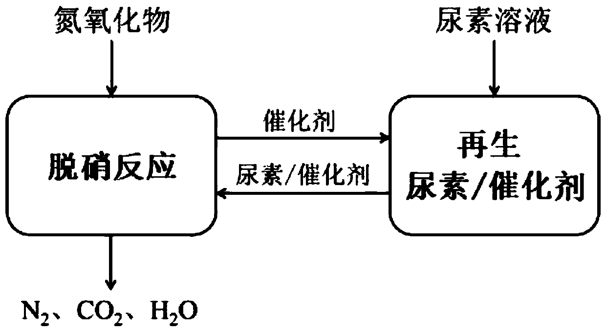
[0046] Loading urea on the surface of activated carbon or activated carbon fiber can be directly used for low-temperature flue gas denitration treatment. Among them, activated carbon or activated carbon fiber is used as a catalyst to promote the reaction of nitrogen oxides in low-temperature flue gas with urea loaded on the catalyst to generate non-toxic nitrogen, water vapor and carbon dioxide. The specific reaction is as follows:

[0047] 6NO+2CH 4 N 2 O→5N 2 +2CO 2 +4H 2 o

[0048] 2NO+O 2 →2NO 2

[0049] 6NO 2 +4CH 4 N 2 O→7N 2 +4CO 2 +8H 2 o

[0050] NO+NO 2 +CH 4 N 2 O→2N 2 +CO 2 +2H 2 o

[0051] Preferably, the catalyst is selected from activated carbon loaded with metal oxides or activated carbon fibers loaded with metal oxides, w...


PUM


Abstract

The invention relates to a method for removing nitrogen oxides from low-temperature flue gas, which comprises the following steps of: S1, preparing at least two reactors containing a catalyst and urealoaded on the catalyst, and dividing the reactors into a reaction group and a to-be-reacted group.S2, introducing low-temperature flue gas into the reaction group for denitration reaction; introducing the low-temperature flue gas into the reaction group for denitration reactionwhen urea in the reaction group is consumed to a preset value, and supplementing the urea in the reaction group.S3, introducing the low-temperature flue gas into the to-be-reacted group for denitration reactionwhen urea in the to-be-reacted group is consumed to a preset value, and supplementing the urea in the to-be-reacted group; and S4, alternately introducing the low-temperature flue gas into the reaction group and the to-be-reacted group according to the mode so as to achieve the continuous denitration of the low-temperature flue gas.The invention also provides a system for removing nitrogen oxides from low-temperature flue gas according to the method.The removal of nitrogen oxides in low-temperature flue gas is achieved, the problem of ammonia escape is avoided, and meanwhile, the continuous denitration of low-temperature flue gas and the repeated use of the catalyst are ensured.

Description

technical field [0001] The invention belongs to the technical field of environmental protection and flue gas purification, and in particular relates to a method and system for removing nitrogen oxides from low-temperature flue gas. Background technique [0002] As one of the main pollutants in the atmosphere, nitrogen oxides NO X Emissions mainly come from stationary sources such as thermal power stations and steel mills, and mobile sources such as motor vehicle exhaust. The emission of nitrogen oxides will cause acid rain, ozone depletion, photochemical pollution and human respiratory diseases, seriously endangering the environment and human health. NO X The main component of nitrogen oxides is nitric oxide. Among many nitrogen oxide removal technologies, selective catalytic reduction SCR is widely used in industry due to its high denitrification efficiency, and it is mainly used for the reduction of selective catalytic reduction. Ammonia NH 3 and urea. [0003] NH 3 ...

Claims


Application Information

Patent Timeline
IPC IPC(8): B01D53/90B01D53/56
Inventor 于庆波刘凯杰秦勤
Owner NORTHEASTERN UNIV
Why Eureka
Try Eureka