Dual-regenerative flue gas treatment system
A flue gas treatment system and regeneration system technology, applied in the direction of dispersed particle separation, chemical instruments and methods, separation methods, etc., can solve the problems of inability to deeply utilize the large amount of latent heat of flue gas water vapor, waste of energy and water resources, high investment costs, etc. problems, achieve good social and economic impacts, reduce operating costs, and save water resources
- Summary
- Abstract
- Description
- Claims
- Application Information
AI Technical Summary
Problems solved by technology
Method used
Image

Examples
Embodiment 1
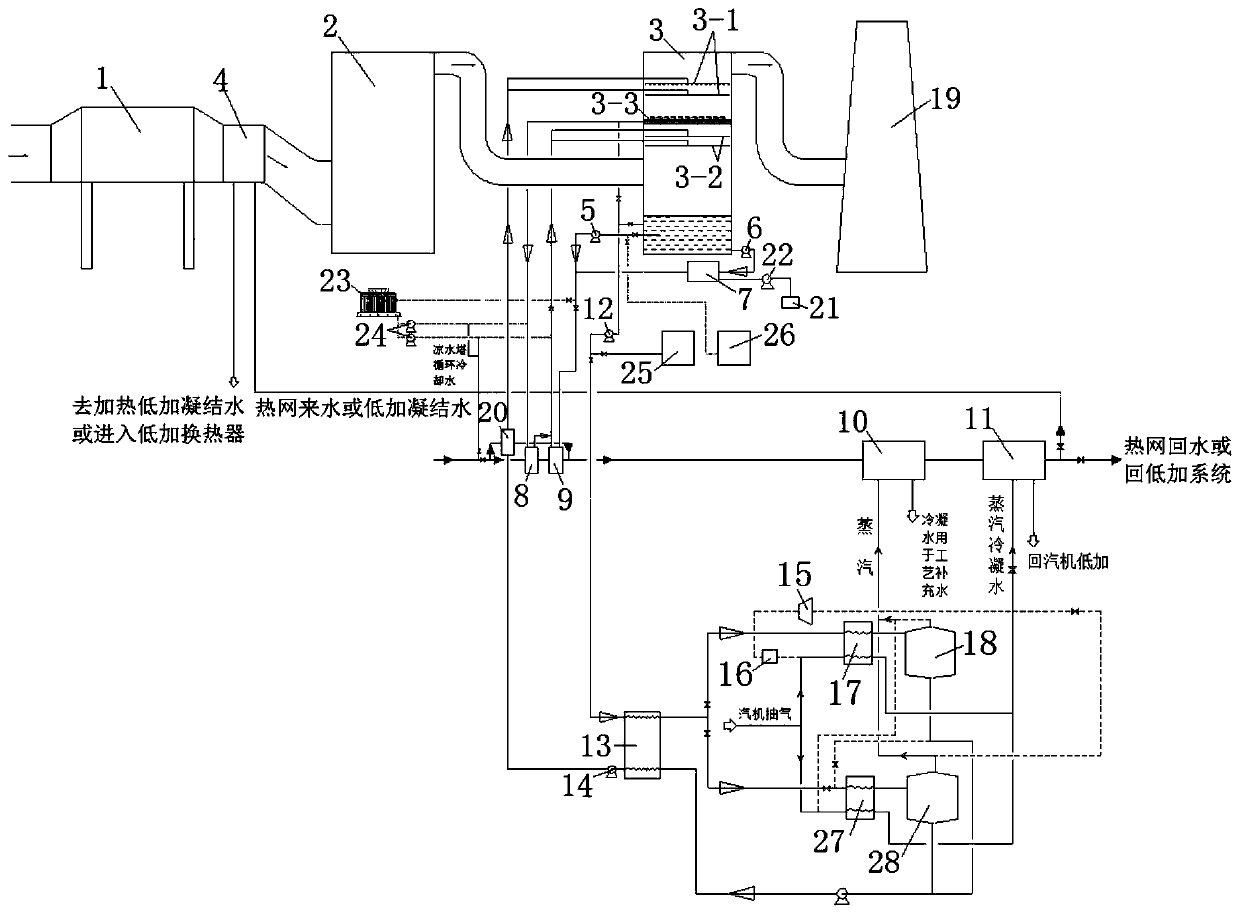
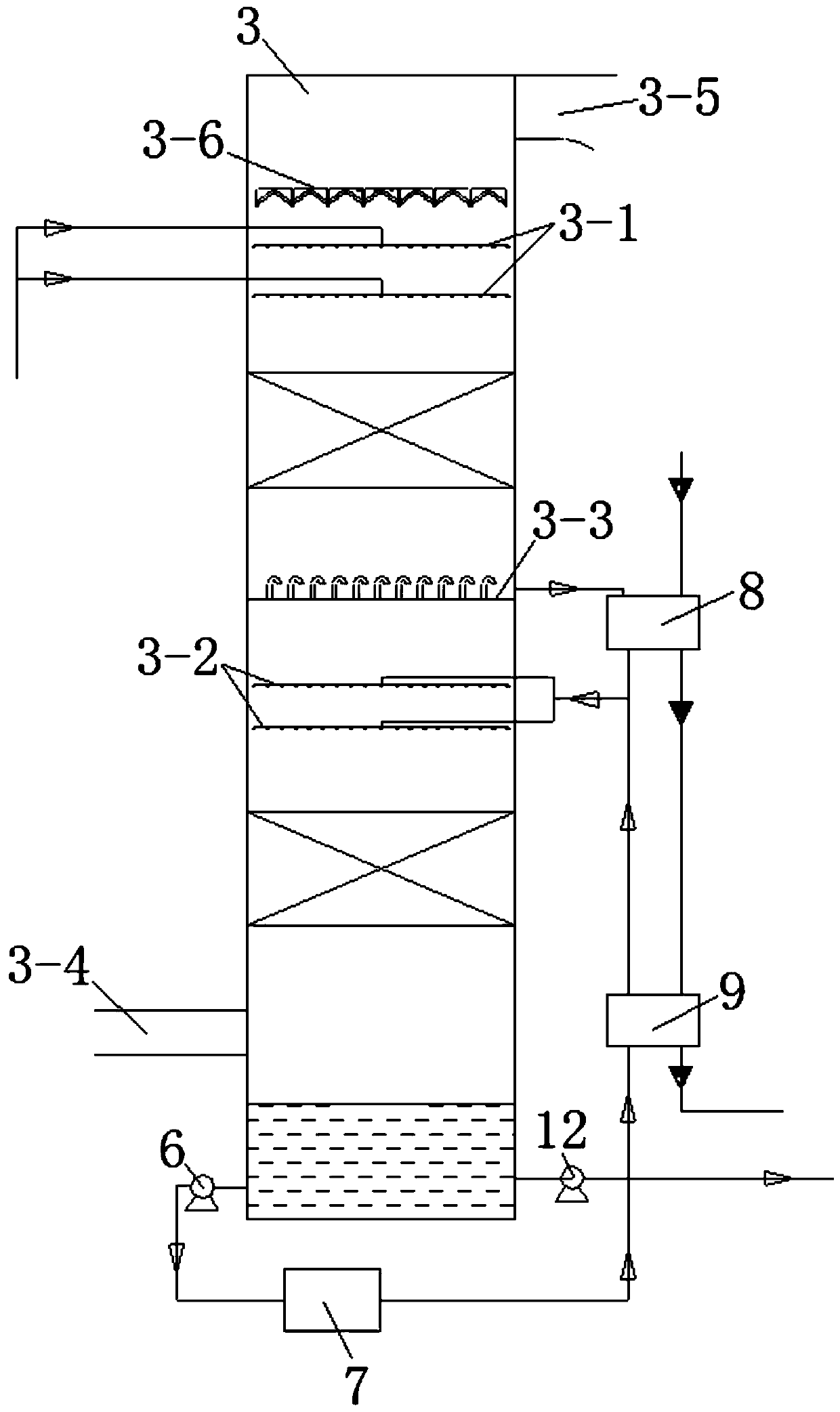
[0054] This embodiment provides a dual regeneration flue gas treatment system, such as figure 1 and 2 As shown, it includes a dedusting device 1, a desulfurization device 2 and an absorption device 3 connected in sequence. For example, the dedusting device 1 can be an electric precipitator, the desulfurization device 2 can be a desulfurization tower, the absorption device 3 can be an absorption tower, and the absorption tower can be a desulfurization tower. Empty tower or packed tower, when it is a packed tower, the packing can be single layer or multi-layer, use the packing as the gas-liquid contact surface, when it is an empty tower, use the empty tower to spray to form the gas-liquid contact surface, the lower part of the absorption device 3 The flue gas inlet 3-4 is set, the flue gas outlet 3-5 is set on the upper part, and also includes,
[0055] The first circulation circuit, its liquid inlet port communicates with the bottom of the absorption device 3, and the liquid o...
Embodiment 2
[0078] This embodiment provides a dual regeneration flue gas treatment system. On the basis of the above-mentioned embodiment 1, in order to improve the heat exchange effect, the sensible heat in the original flue gas and the latent heat of the clean flue gas water vapor are fully recovered, and the The waste liquid is fully regenerated, and also includes a second heat exchanger 9. The lower part of the absorption device 3, the second heat exchanger 9, and the second spray unit 3-2 are connected in sequence to send the dilute solution into the first Second spray unit 3-2; meanwhile, in order to filter and modulate the concentrated solution as the absorption liquid in the absorption device, it also includes a solution filtration and conditioning system 7, the bottom of the absorption device 3, the solution filtration and conditioning system 7, the second The heat exchanger 9 and the second spray unit 3-2 are connected in sequence, so that the dilute solution is sent to the secon...
Embodiment 3
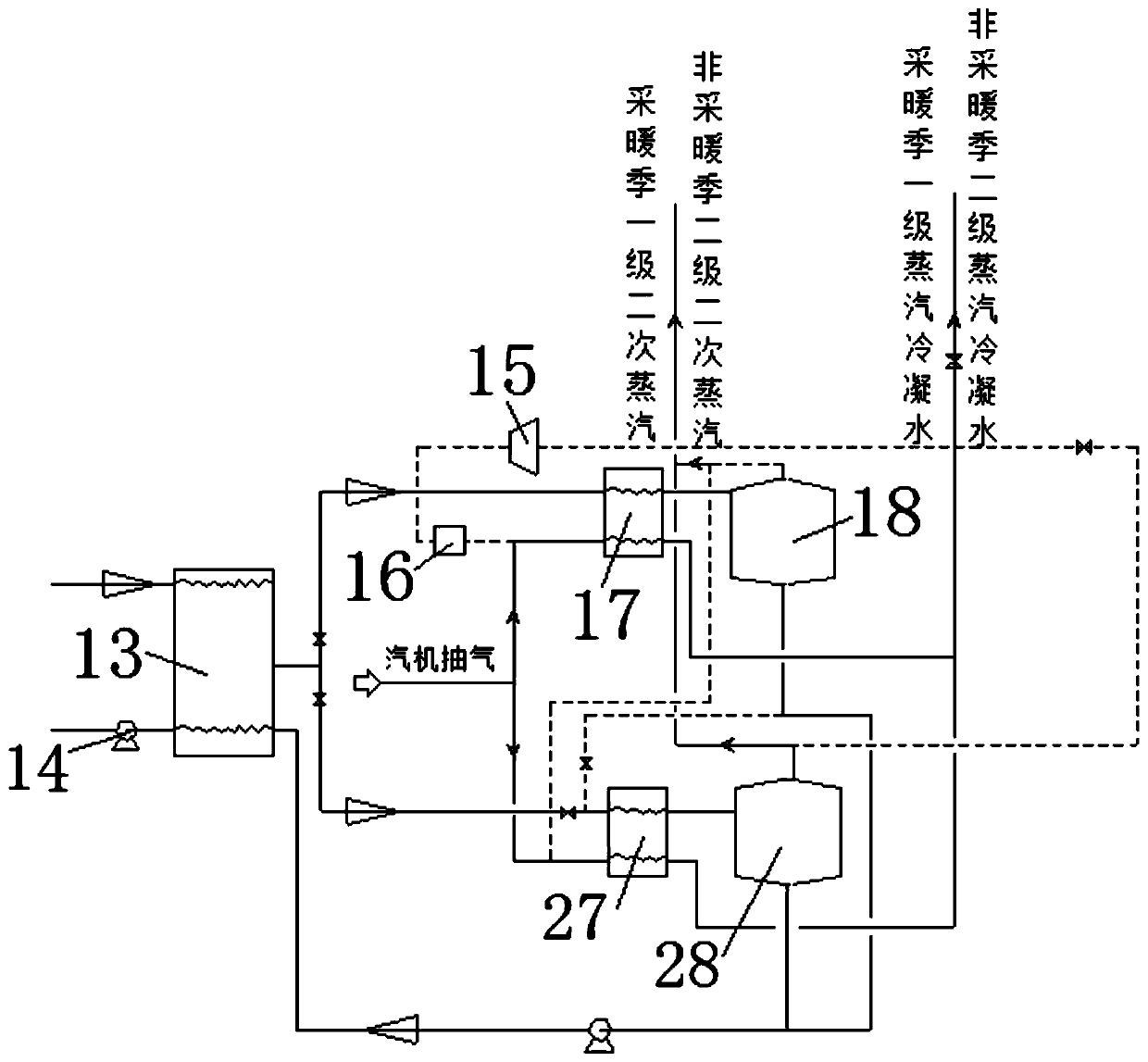
[0080] This embodiment provides a dual regeneration flue gas treatment system, on the basis of the above embodiment 1 or 2, it also includes a third heat exchanger 10 and a fourth heat exchanger 11, the first heat exchanger 8, the second heat exchanger The second heat exchanger 9, the third heat exchanger 10, and the fourth heat exchanger 11 are connected in sequence, so that the incoming water from the heating network or the condensed water at low temperature can pass through the first heat exchanger 8, the second heat exchanger 9, and the fourth heat exchanger in sequence. Three heat exchangers 10 and a fourth heat exchanger 11, and exchange heat with the substances entering the corresponding heat exchangers;
[0081] Further, the sixth heat exchanger 17 and / or the eighth heat exchanger 27 are communicated with the fourth heat exchanger 11 respectively, so as to transfer the exhaust condensed water of the sixth heat exchanger 17 and / or the eighth heat exchanger 27 After bein...
PUM
 Abstract
Description
Claims
Application Information
 - R&D
- Intellectual Property
- Life Sciences
- Materials
- Tech Scout
- Unparalleled Data Quality
- Higher Quality Content
- 60% Fewer Hallucinations
Browse by: Latest US Patents, China's latest patents, Technical Efficacy Thesaurus, Application Domain, Technology Topic, Popular Technical Reports.
© 2025 PatSnap. All rights reserved.Legal|Privacy policy|Modern Slavery Act Transparency Statement|Sitemap|About US| Contact US: help@patsnap.com