A high-precision method for measuring interface contact thermal resistance by bidirectional heat flow method

A technology of contact thermal resistance and heat flow method, which is applied in the field of testing, can solve problems such as not being perfect, and achieve the effects of improving test accuracy, facilitating thermal protection treatment, and realizing one-dimensional heat conduction

Active Publication Date: 2022-08-05
GUILIN UNIV OF ELECTRONIC TECH
View PDF7 Cites 0 Cited by
  • Summary
  • Abstract
  • Description
  • Claims
  • Application Information

AI Technical Summary

Problems solved by technology

In short, the above-mentioned steady-state method and unsteady-state method are mainly aimed at measuring the thermal contact resistance of materials at room temperature and not exceeding 600°C, but the thermal contact resistance under high temperature conditions has not been well established due to many key issues involved. Higher precision test method can be used for actual test

Method used


Image

  • A high-precision method for measuring interface contact thermal resistance by bidirectional heat flow method
  • A high-precision method for measuring interface contact thermal resistance by bidirectional heat flow method
  • A high-precision method for measuring interface contact thermal resistance by bidirectional heat flow method

Examples


Embodiment 1

[0037] The high-precision test method for measuring the interface contact thermal resistance by the bidirectional heat flow method of the present invention, the specific steps are as follows:

[0038] The first step, the preparation of the test equipment:

[0039] The upper and lower pairs of samples to be tested (the lower sample pair is sample 1 and sample 2, and the upper sample pair is sample 3 and sample 4) are vertically installed on the center of the heating body symmetrically up and down. Between the two set refrigeration blocks, the heating body is arranged in the middle position, in order to accurately obtain the heat flow value, four heat flow meters are added between the upper and lower two sample pairs and the heating body and the refrigeration block;

[0040] The structure diagram of the test device of the present invention is as follows figure 1As shown in the figure, the test device is similar to the American national standard ASTM E1225, and it has been furth...

Embodiment 2

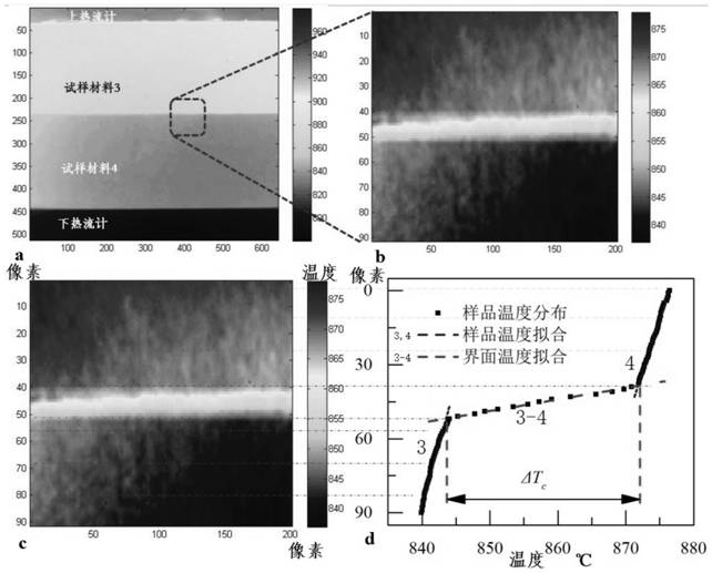
[0058] The imaging of the upper sample pair (sample 3 and sample 4) and its temperature data processing method are as follows: Figure 4 shown. Specifically, the size of the captured temperature field image is as follows: Figure 4 a, the image is 512 pixels (the axial direction of the sample to be tested is the longitudinal direction) × 640 pixels (the cross-sectional direction of the sample to be tested is the horizontal direction), and the corresponding actual size is about 5120 μm × 6400 μm, Figure 4 In a, from top to bottom are the upper heat flow meter, sample material 3 and sample material 4. In order to improve the value accuracy of the interface temperature difference and heat flow, the Figure 4 The image is extracted at the contact interface of a, and the extracted image is 90 pixels (the axial direction of the sample to be tested) × 100 pixels (the direction of the cross-section of the sample to be tested). Figure 4 b, The temperature distribution at the conta...


PUM


Abstract

The invention discloses a high-precision method for measuring interface contact thermal resistance by a bidirectional heat flow method, which belongs to the technical field of testing. In the bidirectional heating heat flow method adopted in the present invention, a heating body is arranged at the center of the test body, and multiple layers are arranged around the heating body. Compared with the end, the vacuum heat shield is easier to be insulated, and realizes one-dimensional heat conduction of the sample pair. The invention can measure the interface contact thermal resistance of two groups of samples to the material at the same time; and adopts advanced non-contact thermal imaging technology to perform average processing of multiple data points, which can realize high temperature, transient and micro-nano scales with higher precision The high-precision interface contact thermal resistance test can be realized, and the interface contact thermal resistance test can be realized from normal temperature to 2700℃.

Description

technical field [0001] The invention belongs to the technical field of testing, in particular to a method for testing interface contact thermal resistance. Background technique [0002] The solid-solid interface contact heat transfer phenomenon under high temperature conditions widely exists in the fields of aerospace, energy power, and thermonuclear reactions. The precise determination of the contact thermal resistance parameters is particularly important for the safe and reliable design of the device or system. Taking hypersonic aircraft as an example, due to aerodynamic heating, the surface temperature of the aircraft will exceed 1000°C, and a thermal protection system needs to be installed to ensure the safety of the aircraft. , the high-temperature interface contact resistance between thermal protection materials is one of the key parameters in the design of thermal protection systems for hypersonic aircraft. In the past, due to the lack of testing methods and systems...

Claims


Application Information

Patent Timeline
Patent Type & Authority Patents(China)
IPC IPC(8): G01N25/20
Inventor 张平李强宣益民马伟陈孟君黄勇史波杨道国
Owner GUILIN UNIV OF ELECTRONIC TECH
Why Eureka
Try Eureka