Drilling fluid displacement determination method meeting cleaning requirement of special-shaped borehole

A technology for determining methods and drilling fluids, applied in wellbore/well components, flushing wellbore, earthwork drilling and production, etc., to achieve the effect of safe and efficient drilling and reasonable control

Active Publication Date: 2019-05-28
CHINA PETROLEUM & CHEM CORP +1
View PDF5 Cites 1 Cited by
  • Summary
  • Abstract
  • Description
  • Claims
  • Application Information

AI Technical Summary

Problems solved by technology

[0007] The purpose of the present invention is to solve the problems existing in the above-mentioned prior art, to provide a method for determining the displacement of drilling fluid that satisfies the cleaning of special-shaped boreholes, and to solve the problem of adjusting the displacement of drilling fluid based on experience or based on regular boreholes at the drilling site

Method used


Image

  • Drilling fluid displacement determination method meeting cleaning requirement of special-shaped borehole
  • Drilling fluid displacement determination method meeting cleaning requirement of special-shaped borehole
  • Drilling fluid displacement determination method meeting cleaning requirement of special-shaped borehole

Examples


Embodiment 1

[0088] (1) Obtain the basic drilling parameters as shown in Table 1:

[0089] Drill diameter D b , m

0.216

Drill pipe outer diameter Dp,m

0.127

Drilling fluid density ρ m, ,kg / m 3

1750

cuttings density ρ d ,kg / m 3

2700

Cuttings equivalent diameter Dd,m

0.005

Well diameter enlargement rate

100%

Initial cuttings concentration at borehole enlargement

10%

[0090] Table 1

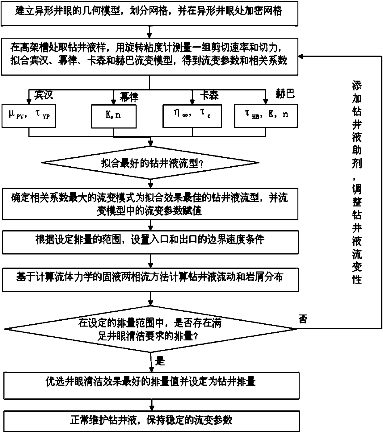
[0091] (2) Establish the geometric model of the special-shaped wellbore, divide the grid, and intensify the grid at the special-shaped wellbore, such as figure 2 shown.

[0092] (3) Drilling fluid samples were taken at the elevated trough, and a set of shear rate and shear force was measured with a rotational viscometer, as shown in Table 2.

[0093]

[0094] Table 2

[0095] According to the shear rate and shear force, regression fit the Bingham flow rheological model, and calculate the correlation coefficient of each...

Embodiment 2

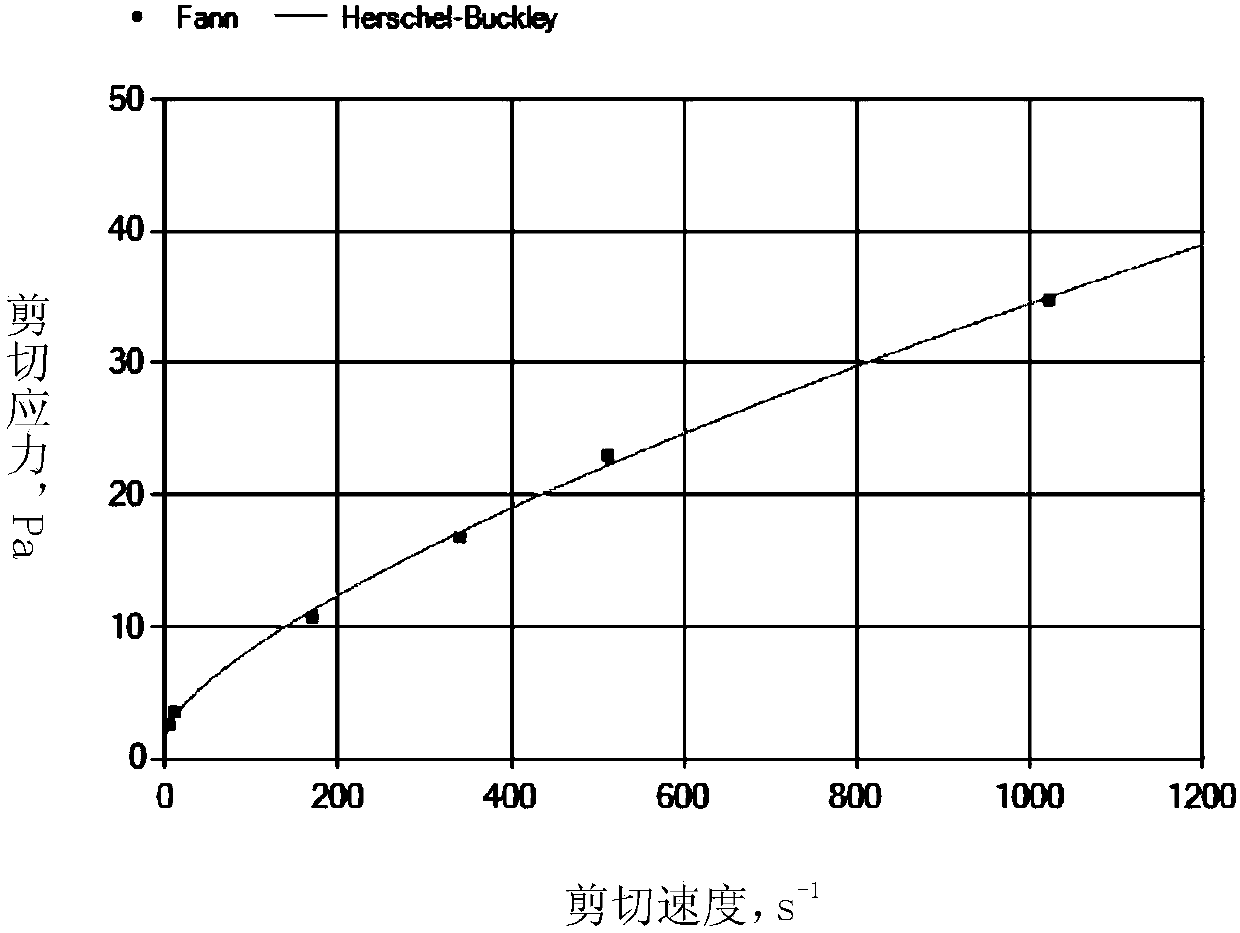
[0102] The basic parameters of drilling and the shape of the special-shaped wellbore are the same as in Example 1. Under the rheological conditions of the drilling fluid in Example 1, there is no displacement range that meets the requirements of wellbore cleaning. In Example 2, by adding drilling fluid additives , to adjust the rheology of drilling fluid. The adjusted drilling fluid rheology is shown in Table 4.

[0103] Rotational viscometer speed, r / min

600

300

200

100

6

3

Shear rate, / s

1022

511

340.7

170.3

10.2

5.11

Rotational viscometer reading θ

172

128

99

71

36

27

Shear force τ, Pa

87.9

65.4

50.6

36.3

18.4

13.8

[0104] Table 4

[0105] According to the shear rate and shear force, four rheological models were fitted by regression, and the Herba-Ba model with the largest correlation coefficient was determined as the rheological type for calculation, as shown in Tab...

Embodiment 3

[0112] (1) Obtain the basic drilling parameters as follows:

[0113] Drill diameter D b , m

0.216

Drill pipe outer diameter Dp,m

0.127

Drilling fluid density ρ m, ,kg / m 3

1800

cuttings density ρ d ,kg / m 3

2700

Cuttings equivalent diameter Dd,m

0.005

Well diameter enlargement rate

79%

Initial cuttings concentration at borehole enlargement

10%

[0114] Table 6

[0115] (2) Establish the geometric model of the special-shaped wellbore, divide the grid, and intensify the grid at the special-shaped wellbore, such as Figure 13 shown.

[0116] (3) Drilling fluid samples were taken at the elevated trough, and a set of shear rates and shear forces were measured with a rotational viscometer, as shown in Table 7.

[0117]

[0118] Table 7

[0119] According to the shear rate and shear force, four rheological models are regression fitted, and the correlation coefficients of each model are calculat...


PUM


Abstract

The invention provides a drilling fluid displacement determination method meeting the cleaning requirement of a special-shaped borehole, and belongs to the field of well drilling in exploratory development of petroleum and natural gas. The method comprises steps as follows: firstly, a special-shaped borehole geometric model is established on the basis of drilling basic parameters, initial displacement is set, then rock debris concentration distribution in each position of the borehole in a stable state is obtained by numerical calculation, whether the borehole cleaning effect is realized or not is judged according to the rock debris concentration distribution, whether drilling fluid displacement is in a reasonable displacement range or not is judged, if one of judgments is no, drilling fluid rheological property is adjusted, the process is repeated until the drilling fluid displacement meets the requirement for borehole cleaning effect and is in the reasonable displacement range, and at the moment, the drilling fluid displacement is finally determined. According to the method, the defects of an existing empirical method or an annulus hydraulic method based on a regular borehole canbe overcome, and the problem of poor adjustment precision of the drilling fluid displacement in the special-shaped borehole with experience or the annulus hydraulic method on the drilling site can besolved.

Description

technical field [0001] The invention belongs to the field of petroleum and natural gas exploration and development drilling, and in particular relates to a method for determining the displacement of drilling fluid that satisfies the cleaning of special-shaped well holes. Background technique [0002] Drilling fluid is a fluid medium that circulates and carries cuttings during drilling. Wellbore cleanliness refers to the state of cuttings carried in the wellbore during drilling. The state of cuttings carrying in drilling is directly related to drilling speed and downhole safety, and is a very important drilling parameter. During the drilling process, if the cuttings cannot be carried out of the wellbore in time, it may cause downhole complex situations such as difficulty in running in, incomplete running in, and sticking. Therefore, wellbore cleaning has become the primary issue of safe and fast drilling. [0003] Practice has shown that the shape of the wellbore, the disp...

Claims


Application Information

Patent Timeline
IPC IPC(8): E21B21/00E21B21/08
Inventor 林永学路保平陈曾伟
Owner CHINA PETROLEUM & CHEM CORP
Why Eureka
Try Eureka