Chemical solid grinding machine

A solid grinding and grinding machine technology, applied in the fields of food science, cocoa, grain processing, etc., can solve the problems of incomplete grinding, slow development, slow grinding speed, etc., to increase the grinding speed and avoid the effect of incomplete grinding

Pending Publication Date: 2019-05-28
安徽英特力工业工程技术有限公司
View PDF0 Cites 0 Cited by
  • Summary
  • Abstract
  • Description
  • Claims
  • Application Information

AI Technical Summary

Problems solved by technology

[0002] A branch of chemistry that studies the preparation, composition, structure, and properties of solid substances. Although it has begun to study chemical reactions involving solid substances as early as the 1920s, due to the lack of experimental means to detect the internal microstructure of solid phases, it has developed Slowly, in the 1960s, some new science and technology emerged, requiring more and more solid materials with special properties, and raised many problems that needed to be explored and urgently resolved in terms of the preparation, structure and properties of solid materials; modern science Technology provides a variety of experimental means (such as various spectra, spectra, energy spectra, and mass spectrometry, etc.), so that we can deeply understand the composition and structure of the bulk phase and surface of solids, and test various physical and chemical properties. a new stage of development;
[0003] The chemical solid grinding machine is a device for grinding chemical solid materials. However, most of the grinding discs of existing grinding devices use a single grinding method, the grinding speed is slow, the efficiency is low, and incomplete grinding is prone to occur during grinding. Phenomenon

Method used


Image

  • Chemical solid grinding machine
  • Chemical solid grinding machine
  • Chemical solid grinding machine

Examples


Embodiment 1

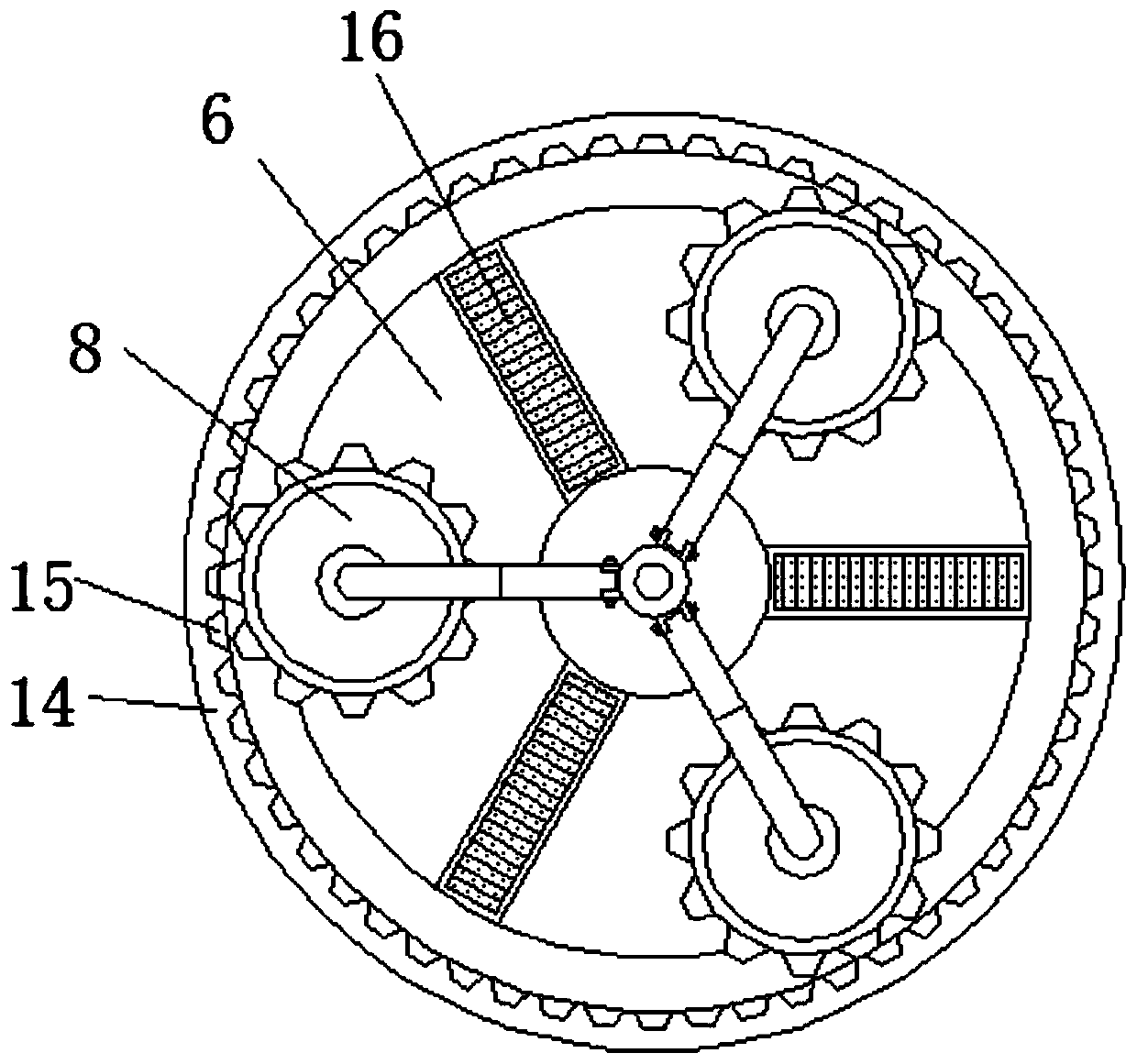
[0028] Embodiment 1, with reference to Figure 1-4 , a chemical solid grinding machine, comprising a grinding machine 14, a bracket 2 is arranged at the lower edge of the grinding machine 14, a servo motor 1 is fixed to the bottom center of the grinding machine 14, and the output shaft of the servo motor 1 runs through the bottom of the grinding machine 14 and extends To the inside of the grinding machine 14, the top of the output shaft of the servo motor 1 is sleeved with a set 13, and the output shaft of the servo motor 1 is located at the top and bottom of the set 13. The positioning card 12 is sleeved, and the outer wall of the set 13 is provided with multiple sets of side stand There are two plates 11 for each group of side risers 11, and a curved rod 10 is connected between the two side risers 11. One end of the bend rod 10 is connected with an upper grinding disc 8 through a bearing 9. The inside of the grinder 14 is horizontal. A lower grinding disc 6 is arranged at th...

Embodiment 2

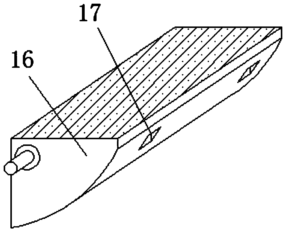
[0031] Embodiment 2, with reference to Figure 2-4 , the upper surface of the lower millstone 6 is equidistantly embedded with a plurality of discharge plates 16, the two ends of the discharge plate 16 are connected with the lower millstone 6 through pin shafts, the bottom of the discharge plate 16 is provided with a mounting groove 17, and the upper surface of the material guide device 4 The surface is located at the place below the discharge plate 16 and is provided with an electric push rod 5. The top of the electric push rod 5 is connected to the inner wall of the installation groove 17 through a pin shaft. The vertical section of the discharge plate 16 is a fan-shaped structure. The upper surface of the discharge plate 16 It is on the same plane as the upper surface of the lower grinding disc 6.

[0032] By adopting the above technical solutions:

[0033] The discharge plate 16 can be rotated. When the discharge plate 16 is rotated to a horizontal state, that is, the upp...

Embodiment 3

[0034] Embodiment 3, with reference to Figure 1-2 , the edge of the upper surface of the lower grinding disc 6 is a raised structure, the diameter of the upper grinding disc 8 is less than or equal to the width of the bottom surface of the lower grinding disc 6, and there are multiple upper grinding discs 8, and the spacing between the plurality of upper grinding discs 8 is equal.

[0035] By adopting the above technical solutions:

[0036] Since the edge of the upper surface of the lower grinding disc 6 is a tilted structure, when the material is scattered on the edge of the upper surface of the lower grinding disc 6, the material will be continuously guided to gather at the center of the lower grinding disc 6 to ensure that all materials can be ground. It can effectively avoid the phenomenon of incomplete grinding of materials.


PUM


Abstract

The invention discloses a chemical solid grinding machine. The chemical solid grinding machine comprises a grinding machine body, wherein supports are arranged at the lower edge of the grinding machine body, a servo motor is fixed at the bottom center of the grinding machine body through a bolt, an output shaft of the servo motor penetrates through the bottom of the grinding machine body and extends into the grinding machine body, and the top of the output shaft of the servo motor is sleeved with an external member; the portions, located at the top and the bottom of the external member, of theoutput shaft of the servo motor are sleeved with positioning clamps; multiple sets of side vertical plates are arranged on the outer wall of the external member, each set has two side vertical plats,and a curved bar is rotationally connected between every two side vertical plates of each set; one end of each curved bar is rotationally connected with an upper grinding plate through a bearing; anda lower grinding plate is arranged at the horizontal center line of the interior of the grinding machine body. The chemical solid grinding machine is suitable for chemical solid grinding. During grinding, the upper grinding plates carry out turnover grinding around the vertical center line of the grinding machine body as well as rotation grinding, the grinding speed is high, and the efficiency ishigh.

Description

technical field [0001] The invention belongs to the technical field of chemical solids, in particular to a chemical solid grinding machine. Background technique [0002] A branch of chemistry that studies the preparation, composition, structure, and properties of solid substances. Although it has begun to study chemical reactions involving solid substances as early as the 1920s, due to the lack of experimental means to detect the internal microstructure of solid phases, it has developed Slowly, in the 1960s, some new science and technology emerged, requiring more and more solid materials with special properties, and raised many problems to be explored and urgently to be solved in the preparation, structure and properties of solid materials; modern science Technology provides a variety of experimental means (such as various spectra, spectra, energy spectra, and mass spectrometry, etc.), so that we can deeply understand the composition and structure of the bulk phase and surfa...

Claims


Application Information

Patent Timeline
Patent Type & Authority Applications(China)
IPC IPC(8): B02C7/00B02C7/11B02C7/12B02C7/16
Inventor 刘兴然
Owner 安徽英特力工业工程技术有限公司
Why Eureka
Try Eureka