
Physical Layer Security Transmission Method Based on Full-duplex Signal Cancellation

A technology of physical layer security and transmission method, which is applied in the field of secure communication, can solve problems such as injecting artificial noise, and achieve the effect of reducing signal-to-noise ratio and increasing bit error rate

Inactive Publication Date: 2021-04-13
HARBIN INST OF TECH +1
View PDF4 Cites 0 Cited by
  • Summary
  • Abstract
  • Description
  • Claims
  • Application Information

AI Technical Summary

Problems solved by technology

[0005] The purpose of the present invention is to solve the problem that the traditional full-duplex physical layer security technology needs to use multiple antennas for beamforming, and needs to find a legal channel null space at the sending end or receiving end to inject artificial noise

Method used


Image

  • Physical Layer Security Transmission Method Based on Full-duplex Signal Cancellation
  • Physical Layer Security Transmission Method Based on Full-duplex Signal Cancellation
  • Physical Layer Security Transmission Method Based on Full-duplex Signal Cancellation

Examples


specific Embodiment approach 1

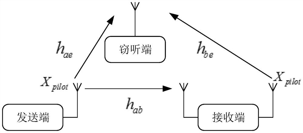
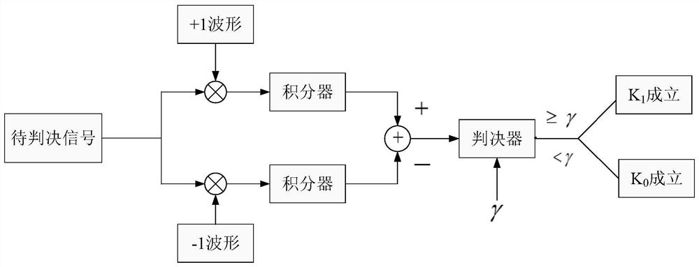
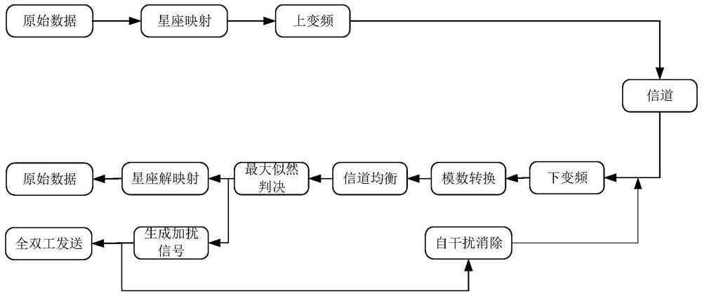
[0032] Specific implementation mode one: as figure 1 with image 3 As shown, the physical layer security transmission method based on full-duplex signal cancellation described in this embodiment includes the following steps:

[0033] Step 1. The receiving end uses full-duplex technology to send the same pilot signal X at the same frequency as the sending end at the same time pilot ;

[0034] Step 2. The receiving end uses the self-interference cancellation technology to remove the self-interference and obtain the pilot sequence received signal Y pilot ;

[0035] Step 3, receive the pilot sequence signal Y obtained in step 2 pilot with pilot signal X pilot The inverse multiplication of is used for channel estimation;

[0036] Step 4: The sending end generates a bit sequence of 0 and 1 to be sent, and the bit sequence is processed and transmitted to the channel;

[0037] Step 5, the receiving end receives the signal in the channel (transmitted to the channel in step 4), a...

specific Embodiment approach 2

[0070] Specific implementation mode two: the difference between this implementation mode and specific implementation mode one is: the specific process of said step two is:

[0071] Pilot signal X sent by the sender pilot After passing through the channel, the pilot sequence received by the receiving end receives the signal Y pilot Expressed as:

[0072] Y pilot = h ab x pilot +Z

[0073] Where: Z is additive Gaussian white noise, h ab is the channel coefficient between the sending and receiving ends.

specific Embodiment approach 3

[0074] Specific implementation mode three: the difference between this implementation mode and specific implementation mode one is: the specific process of the step three is:

[0075] Then use the least squares method for channel estimation, the pilot sequence received signal Y pilot with pilot signal X pilot Multiply the inverse of , and get the channel estimate The expression is:

[0076]

[0077] At the same time, the eavesdropping end also performs corresponding channel estimation, because the eavesdropping end receives the same pilot symbol X from the sending end and the receiving end at the same frequency. pilot ,Such as figure 1 As shown, the channel estimate at the eavesdropping end is where h ae is the channel coefficient between the sending end and the eavesdropping end, h be is the channel coefficient between the receiving end and the eavesdropping end.


PUM


Abstract

The invention discloses a physical layer security transmission method based on full-duplex signal cancellation, which belongs to the technical field of secure communication. The invention solves the problems that the traditional full-duplex physical layer security technology needs to use multiple antennas to perform beamforming and needs to find a legal channel null space at the sending end or receiving end to inject artificial noise. Both the transmitting end and the receiving end of the present invention can only be equipped with a single antenna, without using multi-antenna beamforming technology; in the channel estimation stage, the receiving end simultaneously sends the same pilot signal at the same frequency to scramble the channel estimation at the eavesdropping end, making the eavesdropping The terminal cannot correctly estimate the state information of the eavesdropping channel; use the full-duplex technology to send the anti-signal interference of the original signal to form a signal cancellation effect, and reduce the signal-to-noise ratio of the eavesdropping end; the anti-signal interference can also be controllably deformed, and the anti-signal will be The effect similar to artificial noise is generated, and the method of the invention does not need to find the null space of the legal channel to inject the artificial noise, and the invention can be applied in the technical field of secure communication.

Description

technical field [0001] The invention belongs to the technical field of secure communication, and in particular relates to a method for secure transmission of physical layer signals. Background technique [0002] With the rapid development of computer technology, such as the development of quantum computers, some complex mathematical problems have been solved, and the traditional method of ensuring information security through data encryption is no longer fully competent. In recent years, researchers have gradually considered the use of physical layer coding And signal processing technology to further improve the security of wireless communication. Physical layer security is a security technology based on information theory. Its basic principle is to use the randomness of communication channels and noise to limit the amount of information that can be stolen by non-authenticated terminals. It is theoretically proven to be safe and will not be affected by the growth of computi...

Claims


Application Information

Patent Timeline
Patent Type & Authority Patents(China)
IPC IPC(8): H04L25/03H04L25/02H04B1/525
Inventor 沙学军黄永新李勇房宵杰
Owner HARBIN INST OF TECH
Learn More