
Small antenna and method for machining small antenna and antenna casing

A technology of small antennas and processing methods, which is applied to the structural connection of antennas, loop antennas, and antenna grounding switches, etc. It can solve problems such as size deviation, unguaranteed product quality, and poor product accuracy, so as to prevent uneven wall thickness and reduce the size of the antenna. The effect of radiation potency

Pending Publication Date: 2019-05-24
周春龙
View PDF8 Cites 0 Cited by
  • Summary
  • Abstract
  • Description
  • Claims
  • Application Information

AI Technical Summary

Problems solved by technology

[0002] The current antenna products are mainly circular polarized antennas. The mainstream products of the cylinder have a diameter of Φ=15mm or more, a minimum diameter of Φ=13mm, and a length of more than 100mm. On satellite communication and navigation terminal equipment, such as satellite phones, small As a mobile terminal, the smaller the size the better, and the thinner the diameter the better, and the thinner the antenna, the longer the length will be. For the antenna with a longer length, the processing accuracy is high. During the processing, because the laser Only one surface can be irradiated at a time and the area of ​​the irradiated area is limited. The antenna shell to be processed needs to be rotated, and the product can be carved 4 or 6 times with a laser. The top of the antenna shell is closed, so that it can be exposed to waterproof , the bottom end of the antenna shell is open, which is used to install the jig and drive the antenna shell to rotate around the central axis. If the antenna shell is longer, there will be problems with the coaxiality caused by centrifugal force during the rotation process, and the top of the antenna shell is seriously eccentric. , resulting in poor product accuracy due to dimensional deviation, and product quality cannot be guaranteed. The existing antenna shells are all open at one end. When processing the antenna, only the open end of the shell is fixed, and the closed end is inconvenient to fix. Laser irradiation shell during laser engraving

Method used


Image

  • Small antenna and method for machining small antenna and antenna casing
  • Small antenna and method for machining small antenna and antenna casing
  • Small antenna and method for machining small antenna and antenna casing

Examples


Embodiment Construction

[0036] In order to make the object, technical solution and advantages of the present invention clearer, the present invention will be further described in detail below in conjunction with the accompanying drawings.

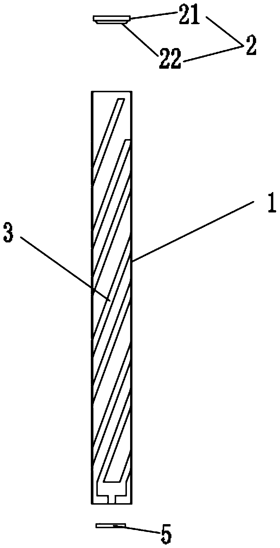
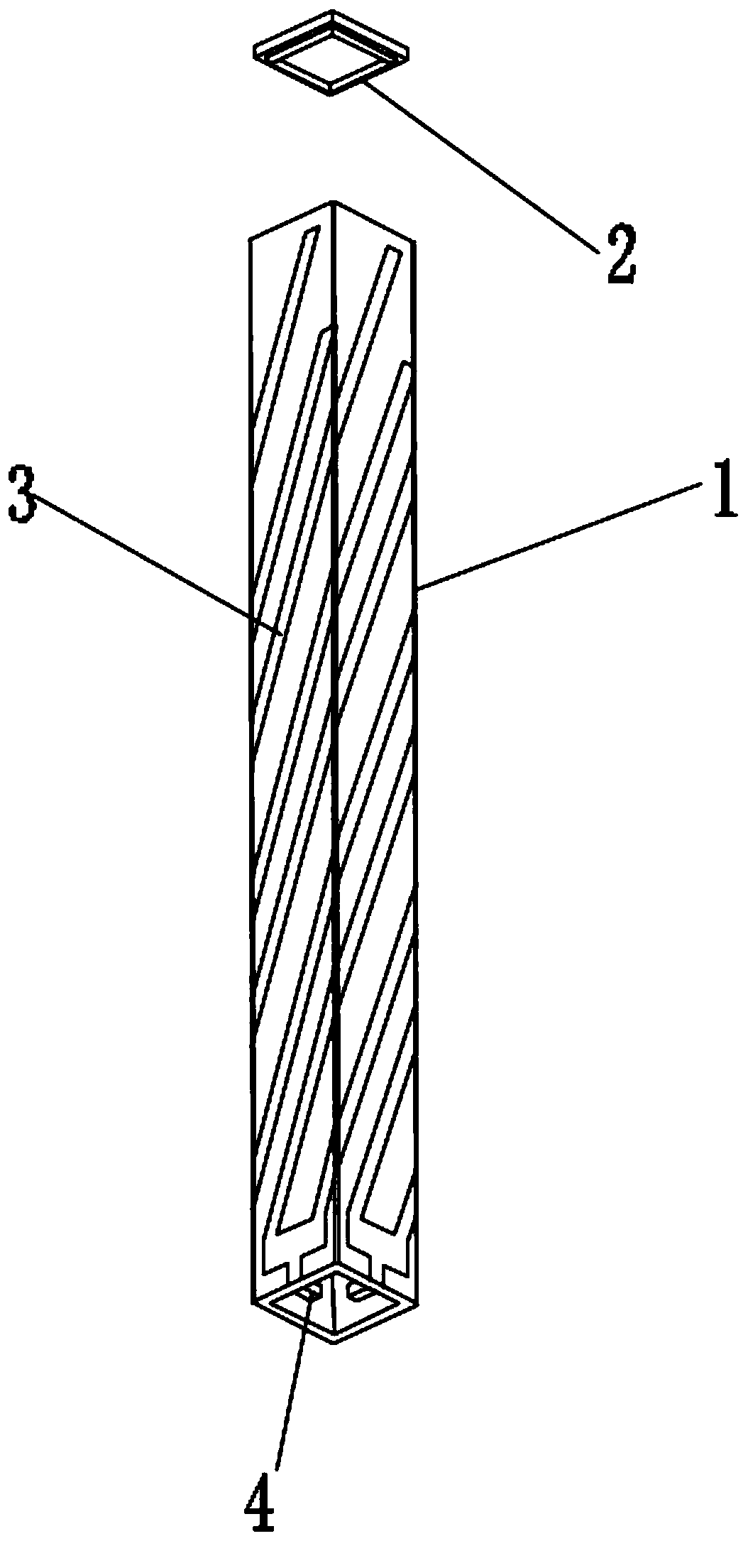
[0037] Such as Figure 1-Figure 3 As shown, the small antenna disclosed in the present invention includes a housing 1, an antenna coil 3, a top cover 2 and a PCB board 5. The housing 1 is columnar, preferably a cylinder or a square prism. The center of the opening and the center of the rear opening are both on the axis of the housing 1, the cylinder formed by the outer wall of the housing 1 and the cylinder formed by the inner wall are coaxial, and the antenna coil 3 is coaxially arranged on the surface of the housing 1, and the antenna coil 3 Spiral, the top cover 2 is connected to the front end of the housing 1, and the top cover 2 is sealed and connected to the front end of the housing 1. The top cover 2 includes an exposed part 21 exposing the front end of the...


PUM

PropertyMeasurementUnit
Outer diameteraaaaaaaaaa

Abstract

The invention discloses a small antenna comprising a casing, an antenna coil and a top cover, wherein the casing is in a columnar shape and a hole extends through the casing; the center of the front-end opening of the casing and the center of the rear-end opening of the casing are both located on the axis of the casing; the antenna coil is coaxially disposed on the surface of the casing; and the top cover covers the front end of the casing, and is in sealed connection with the front end of the casing. The invention also discloses a method for machining the small antenna and an antenna casing.The small antenna and the method provided by the invention can reduce errors in the machining of the antenna, achieve high precision, and realize miniaturization of the antenna.

Description

technical field [0001] The invention relates to an antenna and a processing method thereof, in particular to a small antenna and a processing method of the small antenna and the antenna shell. Background technique [0002] The current antenna products are mainly circular polarized antennas. The mainstream products of the cylinder have a diameter of Φ=15mm or more, a minimum diameter of Φ=13mm, and a length of more than 100mm. On satellite communication and navigation terminal equipment, such as satellite phones, small As a mobile terminal, the smaller the size the better, and the thinner the diameter the better, and the thinner the antenna, the longer the length will be. For the antenna with a longer length, the processing accuracy is high. During the processing, because the laser Only one surface can be irradiated at a time and the area of ​​the irradiated area is limited. The antenna shell to be processed needs to be rotated, and the product can be carved 4 or 6 times with...

Claims


Application Information

Patent Timeline
IPC IPC(8): H01Q1/36H01Q1/38H01Q1/42H01Q1/50H01Q7/00
Inventor 周春龙
Owner 周春龙
Learn More