
Annular artifact correction method based on images before and after reconstruction and CT control system

A correction method, ring artifact technology, applied in the field of image processing, can solve the problems of image resolution reduction, poor energy spectrum CT effect, incomplete correction, etc., and achieve the effect of wide application range

Active Publication Date: 2019-05-24
XIDIAN UNIV
View PDF3 Cites 7 Cited by
  • Summary
  • Abstract
  • Description
  • Claims
  • Application Information

AI Technical Summary

Problems solved by technology

[0006] (2) Using the ring artifact correction method of images before and after reconstruction, the two-step method is used to correct the ring artifact, which is not effective for spectral CT based on photon counting detectors
[0007] The difficulty and significance of solving the above-mentioned technical problems: If correction is performed in the sinusoidal domain, a large number of horizontal stripes shown by the inconsistency of the response of the entire detector between various angles of the photon-counting detector cannot be used for the photon-counting detector. Spectral CT images are well improved, and this method is not corrected thoroughly, and it is easy to bring new artifacts
If a coordinate transformation is used in the reconstructed image domain, whether it is from a polar coordinate system to a rectangular coordinate system or its inverse transformation, interpolation operations must be used, and the interpolation algorithm itself is inaccurate data estimated by surrounding data , so not only the original image information has been lost twice in the coordinate transformation, but the image resolution will inevitably decrease
If the filter template is used when smoothing in polar coordinates, there will also be certain limitations on the number of ring artifacts to be corrected

Method used

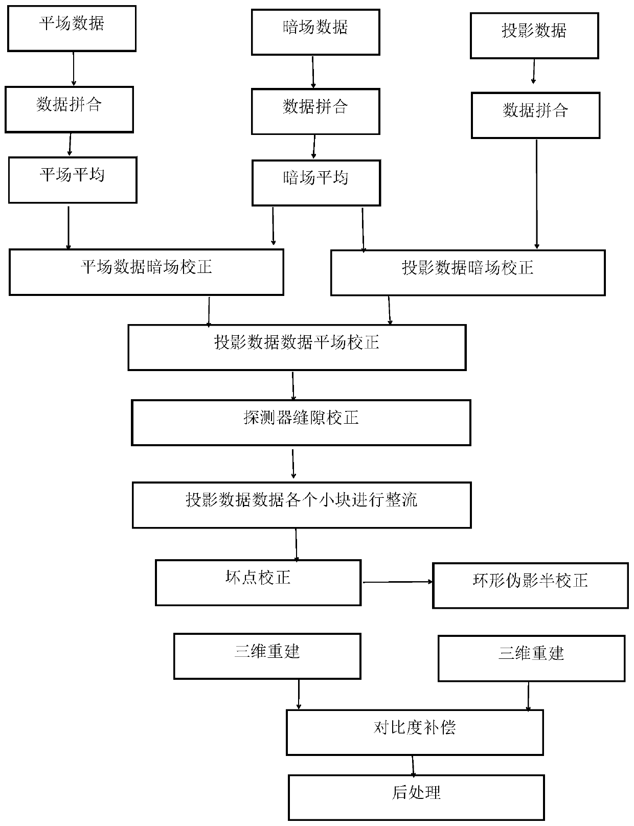

Image

  • Annular artifact correction method based on images before and after reconstruction and CT control system
  • Annular artifact correction method based on images before and after reconstruction and CT control system
  • Annular artifact correction method based on images before and after reconstruction and CT control system

Examples


Embodiment Construction

[0052] In order to make the object, technical solution and advantages of the present invention more clear, the present invention will be further described in detail below in conjunction with the examples. It should be understood that the specific embodiments described here are only used to explain the present invention, not to limit the present invention.

[0053] The present invention utilizes the existing characteristics of the energy spectrum CT system based on the photon counting detector, improves the prior art, and obtains good ring artifact correction results.

[0054] The application principle of the present invention will be described in detail below in conjunction with the accompanying drawings.

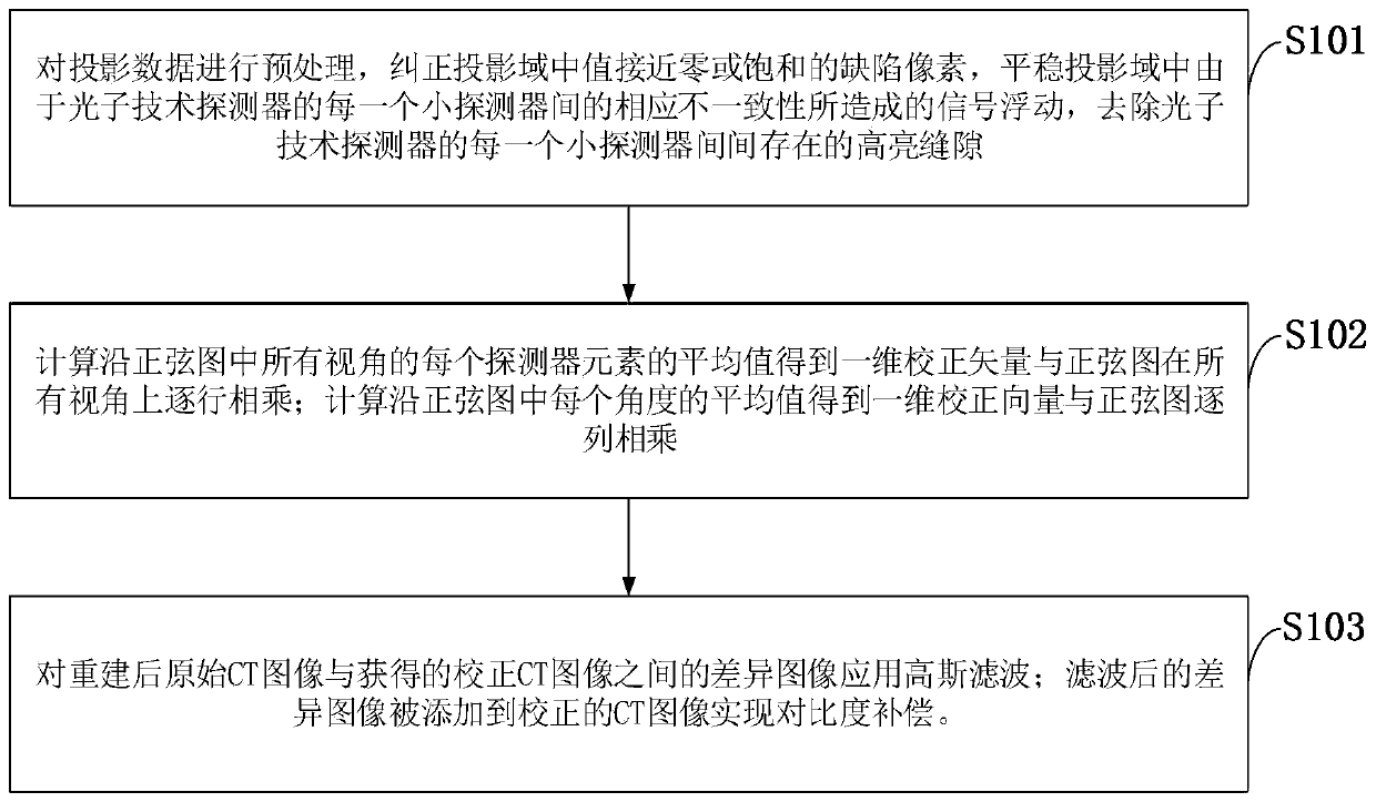
[0055] Such as figure 1 As shown, the method for correcting ring artifacts based on images before and after reconstruction provided by an embodiment of the present invention includes the following steps:

[0056] S101: Preprocess the projection data, correct the defectiv...


PUM


Abstract

The invention belongs to the technical field of image processing, and discloses an annular artifact correction method based on images before and after reconstruction and a CT control system. The method comprises the steps of preprocessing projection data; Calculating an average value of each detector element along all visual angles in the sine graph to obtain a one-dimensional correction vector, and multiplying the one-dimensional correction vector by the sine graph line by line on all the visual angles; Calculating an average value along each angle in the sine map to obtain a one-dimensionalcorrection vector, and multiplying the one-dimensional correction vector by the sine map column by column; Applying Gaussian filtering to a difference image between the reconstructed original CT imageand the obtained corrected CT image; The filtered difference image is added to the corrected CT image to realize contrast compensation. According to the defect that the signal of the energy spectrumCT system based on the photon counting detector is unstable, a multi-step algorithm is introduced, the method is more suitable for the image characteristics of energy spectrum CT image data, and the annular artifact of the image is greatly improved.

Description

technical field [0001] The invention belongs to the technical field of image processing, and in particular relates to a ring artifact correction method and a CT control system based on images before and after reconstruction. Background technique [0002] At present, the existing technology commonly used in the industry is as follows: ring artifacts usually appear in images acquired by a computed tomography (CT) system and exist in the form of concentric circles, seriously reducing the quality of the obtained images. Ringing artifacts can be caused by a variety of causes, including defective detector pixels, nonlinear response of pixels, inconsistencies in detector gain, structural patterns of the detector and X-ray source, systematic changes over time and temperature conditions factors such as changes. [0003] There have been a lot of researches on ring artifact correction methods, and ring artifact correction can be performed on sinusoidal domain and CT image domain. In ...

Claims


Application Information

Patent Timeline
Patent Type & Authority Applications(China)
IPC IPC(8): G06T11/00
Inventor 朱守平闫秋娟时煜孟凡珍
Owner XIDIAN UNIV
Learn More