
Full framing protection system and supporting method thereof

A technology of full support and protection system, which is applied in the direction of earthwork drilling, shaft lining, tunnel lining, etc. It can solve the problems of cumbersome construction, safety hazards, and long construction duration of the anchor net spraying division, and achieve convenient side wall monitoring support The effect of protecting construction operations, ensuring the safety of construction personnel and equipment, and ensuring construction safety is simple and efficient

Active Publication Date: 2019-05-24
中铁十四局集团建筑工程有限公司 +1
View PDF3 Cites 0 Cited by
  • Summary
  • Abstract
  • Description
  • Claims
  • Application Information

AI Technical Summary

Problems solved by technology

[0004] At present, in most cases, comprehensive protection is not carried out, and temporary protective scaffolding is only erected at the construction site, which has low protection capacity and is unsafe; where dangerous rocks in karst caves are seriously developed, it is usually protected by temporary protective scaffolding to carry out comprehensive anchor net spraying protection Or reinforced concrete column protection, but the protection during the construction process is insufficient, it is easy to endanger the safety of personnel and equipment, it is not conducive to the stable monitoring of the roof and surrounding side walls of the karst cave, and there are often construction dead ends, which endanger safety; The problems of column concrete pouring and long solidification period will lead to long construction duration, high construction risk and limited protection ability. In addition, the problem of column roof connection is not easy to solve. Large-scale karst caves are only connected to the outside by the construction opening, and it is impossible to transport large-scale equipment into the karst cave.

Method used


Image

  • Full framing protection system and supporting method thereof
  • Full framing protection system and supporting method thereof
  • Full framing protection system and supporting method thereof

Examples


Embodiment Construction

[0062] It should be pointed out that the following detailed description is exemplary and intended to provide further explanation to the present application. Unless defined otherwise, all technical and scientific terms used herein have the same meaning as commonly understood by one of ordinary skill in the art to which this application belongs.

[0063] It should be noted that the terminology used here is only for describing specific implementations, and is not intended to limit the exemplary implementations according to the present application. As used herein, unless the context clearly dictates otherwise, the singular is intended to include the plural, and it should also be understood that when the terms "comprising" and / or "comprising" are used in this specification, they mean There are features, steps, operations, means, components and / or combinations thereof;

[0064] As introduced in the background technology, at present, in most cases, the safety protection steel shed i...


PUM


Abstract

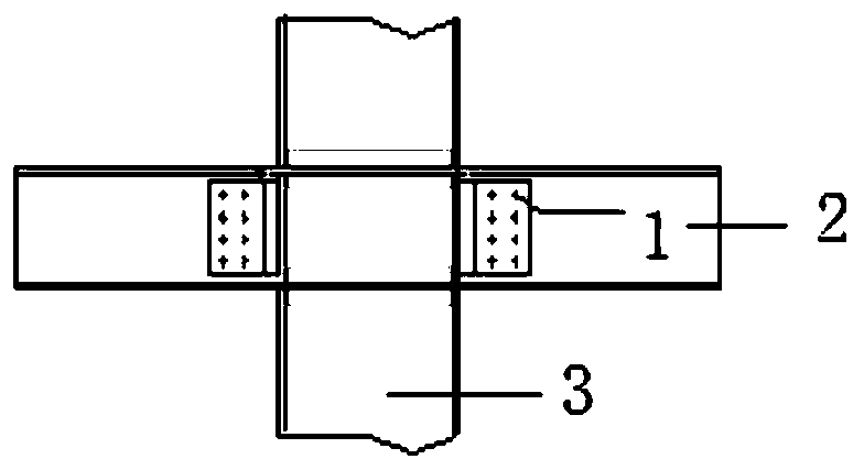
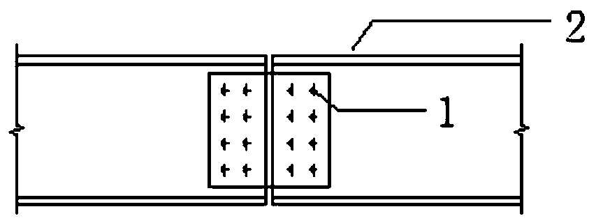
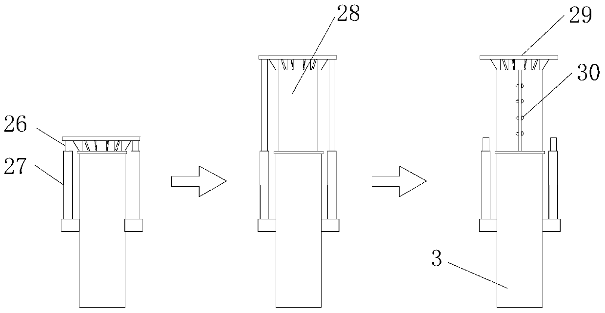
The invention discloses a full framing protection system and a supporting method thereof. The system comprises a plurality of groups of protection frameworks and protection slide frames, each group ofthe protection frameworks form a protection area, and multiple protection areas form karst cave full framing protection. Each group of the protection frameworks includes multiple protection frameworks. Each protection framework comprises a plurality of framework columns, framework beams, top telescopic roof-contacted sections, peripheral wall-contacted sections and protection nets, wherein each framework column comprises multiple sections which are connected together sequentially and vertically; the framework beams are in horizontal arrangement, and two ends of the framework beams are connected with the framework columns through connectors to connect the framework columns into a whole; the top telescopic roof-contacted sections are arranged at tops of the framework columns; the peripheralwall-contacted sections are arranged at wall-contacted ends of the framework beams; the protection nets are arranged at the tops of the protection frameworks. The protection slide frames are arrangedon the protection frameworks and capable of moving along the protection frameworks to provide protection in supporting of the protection frameworks.

Description

technical field [0001] The invention belongs to the field of underground engineering support, and in particular relates to a protective system and a support method for a full hall support, which can be applied to supports such as karst caves and tunnels. Background technique [0002] The statements herein merely provide background information related to the present invention and do not necessarily constitute prior art. [0003] Tunnel construction often encounters karst caves, especially some super-large karst caves. These karst caves have irregular shapes and different characteristics of each karst cave. However, in general, due to long-term geological effects, the walls of the karst caves are broken and easy to fall, threatening the safety of construction personnel. . [0004] At present, in most cases, comprehensive protection is not carried out, and temporary protective scaffolding is only erected at the construction site, which has low protection capacity and is unsafe...

Claims


Application Information

Patent Timeline
Patent Type & Authority Applications(China)
IPC IPC(8): E21D11/14E21D11/15E21D11/10
Inventor 刘同江于明洋孙亚飞王献伟李占先隋渤海朱桂利刘利赵秋林朵生君王军
Owner 中铁十四局集团建筑工程有限公司
Learn More