Method of mounting main and auxiliary trusses of tubular truss structure in intersecting manner

An installation method and technology of pipe trusses, applied in truss structures, truss girders, building structures, etc., can solve the difficulty of guaranteeing the construction quality of truss structures, the low installation efficiency of primary and secondary truss chords, and the impact on the installation quality of intersecting construction, etc. problems, to achieve the effect of convenient installation process of primary and secondary truss intersecting, shortening construction period and reducing construction cost

Inactive Publication Date: 2019-05-24
CHINA HUAYE GROUP
View PDF3 Cites 0 Cited by
  • Summary
  • Abstract
  • Description
  • Claims
  • Application Information

AI Technical Summary

Problems solved by technology

However, although the above-mentioned method meets the requirements of high-altitude pipe truss intersecting construction to a certain extent compared with the original technology, it has been found in long-term practice and construction that using the above-mentioned artificial or inverted chain In the way of pulling, after the secondary truss chord is fed into the installation position, the gap between the openings is too large, and the phenomenon of inclination and unevenness of the opening is prone to occur, which seriously affects the installation quality of the intersecting construction, which in turn leads to the overall failure of the truss structure. Construction quality is difficult to guarantee
[0006] In view of this, the existing technology should be improved to solve the technical problems of the low installation efficiency of the primary and secondary truss chords and the difficulty in ensuring the installation quality in the existing technology

Method used


Image

  • Method of mounting main and auxiliary trusses of tubular truss structure in intersecting manner
  • Method of mounting main and auxiliary trusses of tubular truss structure in intersecting manner
  • Method of mounting main and auxiliary trusses of tubular truss structure in intersecting manner

Examples


Embodiment Construction

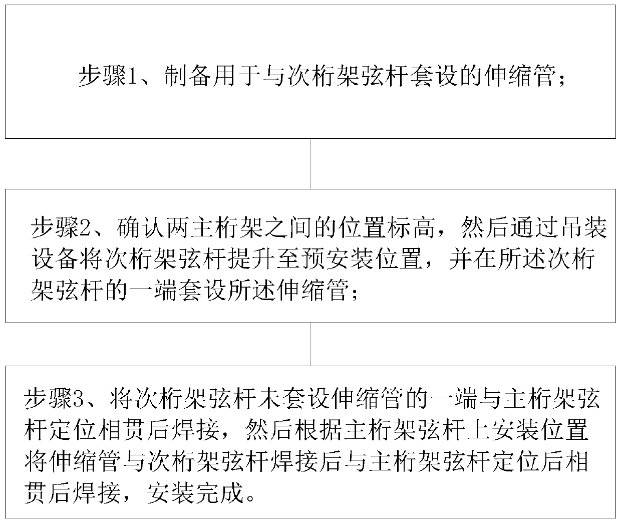
[0019] Embodiments of the intersecting installation method of the primary and secondary trusses of the pipe truss structure according to the present invention will be described below with reference to the accompanying drawings. As those skilled in the art would realize, the described embodiments may be modified in various different ways, all without departing from the spirit and scope of the present invention. Accordingly, the drawings and description are illustrative in nature and not intended to limit the scope of the claims. Also, in this specification, the drawings are not drawn to scale, and like reference numerals denote like parts.

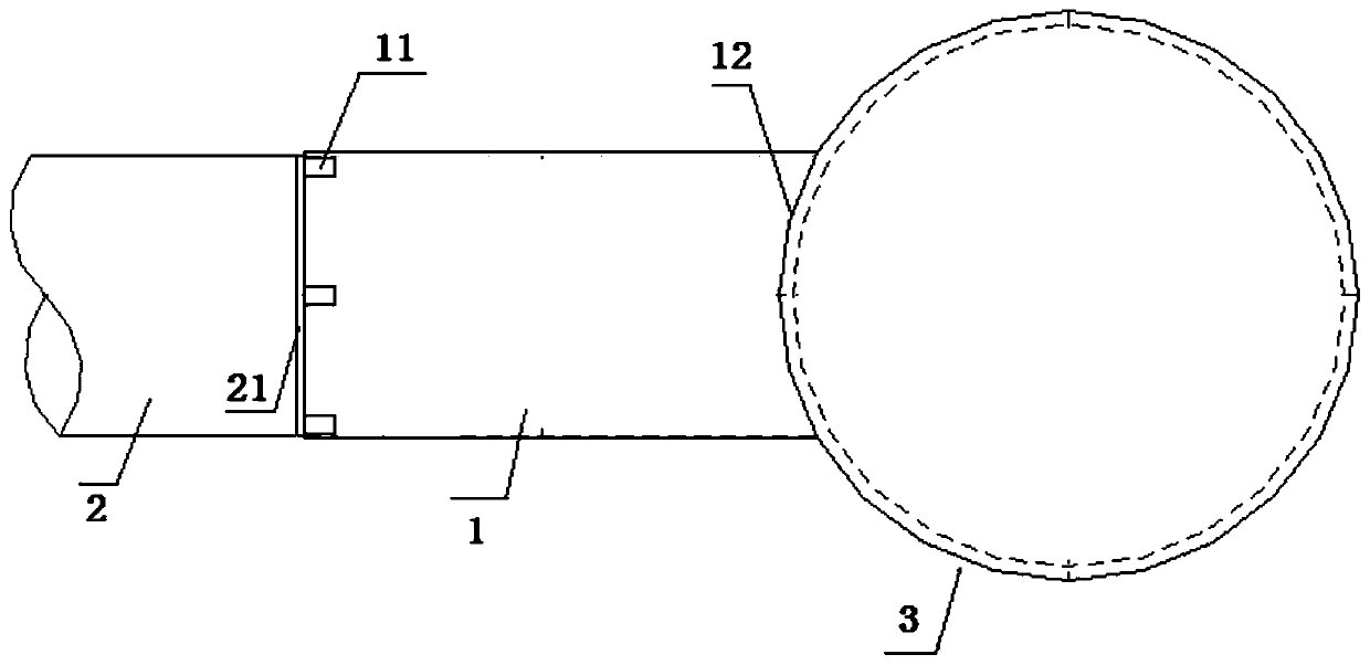
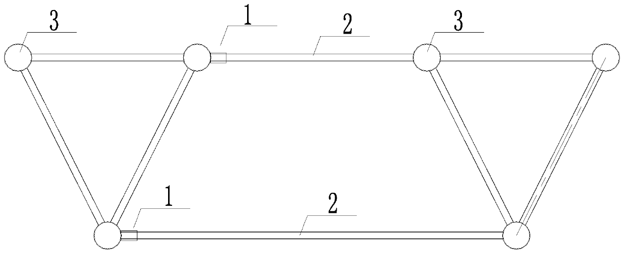
[0020] figure 1 It is a flowchart showing the flow of the method for intersecting the primary and secondary trusses of the pipe truss structure described in one embodiment of the present invention. Such as figure 1 As shown, the intersecting installation method of the primary and secondary trusses of the pipe truss structure described in...


PUM


Abstract

The invention provides a method of mounting main and auxiliary trusses of a tubular truss structure in intersecting manner. The method comprises the steps of 1, producing telescopic tubes to sleeve chord members of auxiliary trusses; 2, determining a positional elevation of two main trusses, lifting the chord members of the auxiliary trusses to pre-mounting positions via lifting equipment, and sleeving one end of each chord member of the auxiliary trusses with one telescopic tube; 3, welding the end, sleeved with no telescopic tube, of each chord member of the auxiliary trusses to one chord member of the corresponding main truss after positioned intersecting, welding the telescopic tubes to the chord members of the auxiliary trusses according to the mounting positions on the chord membersof the main trusses, welding the weldments to the chord members of the main trusses after positioned intersecting, and finishing mounting. The chord members of the main and auxiliary trusses can be mounted and positioned in an aerial operation environment more precisely, chord member mounting speed is evidently increased, construction period of the whole truss structure is shortened, constructionquality is guaranteed, and construction cost can be decreased.

Description

technical field [0001] The invention relates to the technical field of space truss structure construction, in particular to a method for intersecting primary and secondary trusses of a pipe truss structure. Background technique [0002] The truss structure is often used in public buildings such as large-span workshops, exhibition halls, gymnasiums and bridges. The pipe truss is a plane or space structure with triangular units composed of straight rods. The truss members mainly bear axial tension or pressure, so that they can By making full use of the strength of the material, it can save material, reduce self-weight and increase rigidity compared with solid web beams when the span is large. [0003] In the common pipe truss structure in the prior art, its cross-sectional unit form is usually an inverted triangle, in which three main truss chords are connected by webs to form an inverted triangle structure, forming a pipe truss unit, and then through the long straight seconda...

Claims


Application Information

Patent Timeline
Patent Type & Authority Applications(China)
IPC IPC(8): E04C3/02E04G21/14
Inventor 郝玉祥李万生齐祥赵睿伟刘乐时
Owner CHINA HUAYE GROUP
Why Eureka
Try Eureka