Damping valve for a vibration damper

A technology for damping valves and shock absorbers, applied in the field of damping valves

Active Publication Date: 2019-05-21
ZF FRIEDRICHSHAFEN AG
View PDF7 Cites 0 Cited by
  • Summary
  • Abstract
  • Description
  • Claims
  • Application Information

AI Technical Summary

Problems solved by technology

[0005] The object of the present invention is to solve the problems related to the pressure per unit area

Method used


Image

  • Damping valve for a vibration damper
  • Damping valve for a vibration damper
  • Damping valve for a vibration damper

Examples


Embodiment Construction

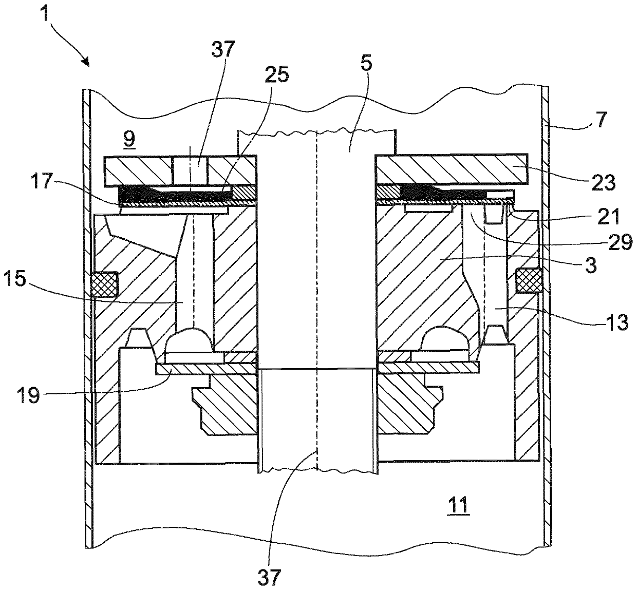
[0023] figure 1 A damping valve 1 for a shock absorber of any desired design is shown. The damping valve 1 includes a damping valve body 3 , and the damping valve body 3 is fixed on a piston rod 5 . The invention is not restricted to this type of embodiment and can be used, for example, in foot valves or also in the area of ​​adjustable damping valves.

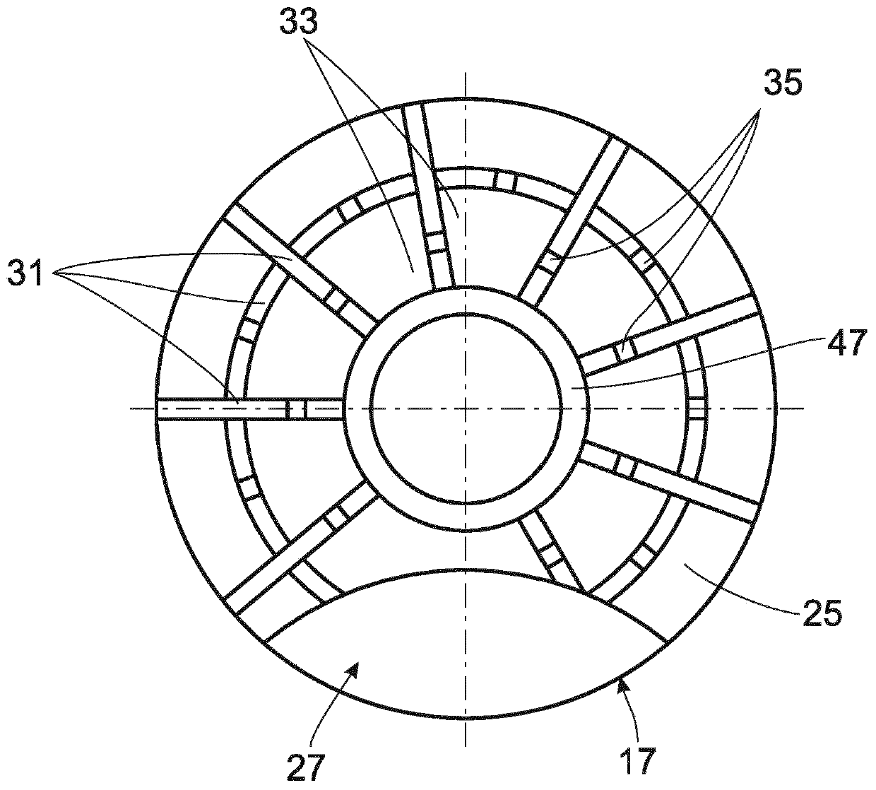
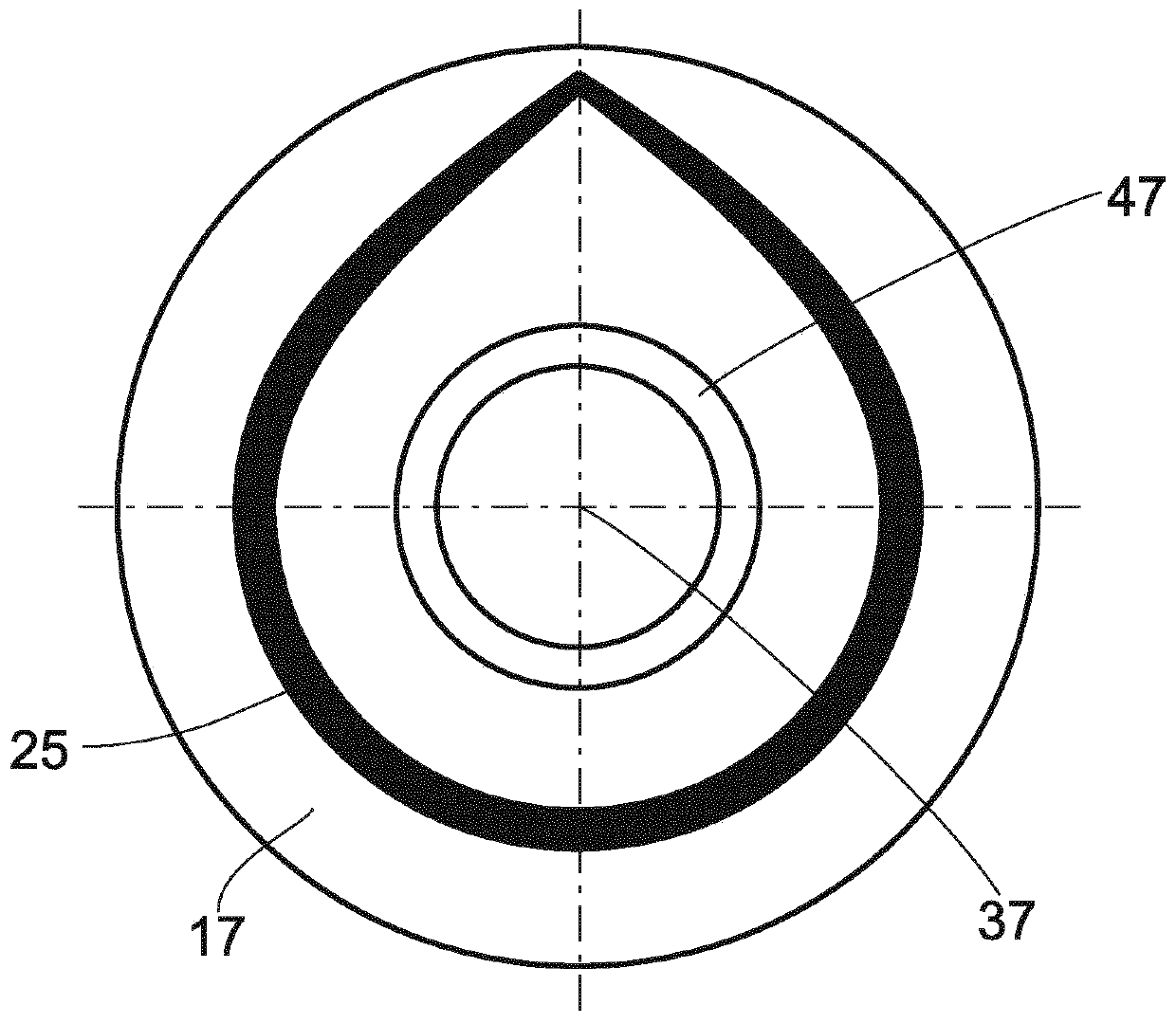
[0024] The damping valve body 3 divides the cylinder 7 of the shock absorber into working chambers 9 , 11 close to the piston rod and remote from the piston rod, both of which are filled with damping medium. Throughflow channels 13 , 15 are embodied in the damping valve body 3 , respectively, for the flow directions on different pitch circles. The configuration of the through-flow channels is merely exemplary. The exit side of the throughflow channel 13 , 15 is at least partially covered by at least one valve disk 17 , 19 .

[0025] Upon inflow into the valve disk 17 starting from the working chamber 11 facing away from th...


PUM


Abstract

The invention relates to a damping valve (1) for a vibration damper, comprising a damping valve body (3) that has at least one duct (13; 15), the discharge side of which is at least partially coveredby at least one elastically deformable valve disc (17), the valve disk (17) further having an another valve element (25, 49) which defines a defined exertion ratio starting from a valve seat surface (21). The additional valve element (25, 49) is formed by the elastic coating of the valve disk (17) which exerts a different supporting force with respect to the valve disk (17) via the arrangement onthe cover surface.

Description

technical field [0001] The invention relates to a damping valve for a shock absorber according to the preamble of claim 1 . [0002] At the same time, a defined, lift-off characteristic of the valve disc from the damping valve body is increasingly sought. Thereby, the noise caused by the sudden lifting of the valve disc can be avoided. Background technique [0003] One means of verification consists in combining two valve disks, wherein the valve disks have edge-side recesses into which the adjacent valve disk can sink. Document US 5 529 154 discloses the construction in different variants. However, the problem associated with this is that the valve disk to be deformed is exposed to high pressure per unit area in the bearing edge region of the adjacent disk. [0004] Document CH 483 587 or document DE 38 16 539 A1 describe a non-return valve having a metal valve disk combined with an elastomer coating. An elastomer coating serves as impact protection. Contents of the i...

Claims


Application Information

Patent Timeline
Patent Type & Authority Applications(China)
IPC IPC(8): F16F9/348
CPCF16F9/3484
Inventor A·科内泽维奇J·罗塞勒
Owner ZF FRIEDRICHSHAFEN AG
Why Eureka
Try Eureka