
Multichannel pipette

A liquid pipette, multi-channel technology, applied in the field of pipette structure and spring mechanism, can solve problems such as unevenness and deformation, and achieve the effect of uniform adhesion

Inactive Publication Date: 2005-12-21
BIOHIT OY FI
View PDF3 Cites 2 Cited by
  • Summary
  • Abstract
  • Description
  • Claims
  • Application Information

AI Technical Summary

Problems solved by technology

The rack may also deform in an uneven manner

Method used


Image

  • Multichannel pipette

Examples


Embodiment Construction

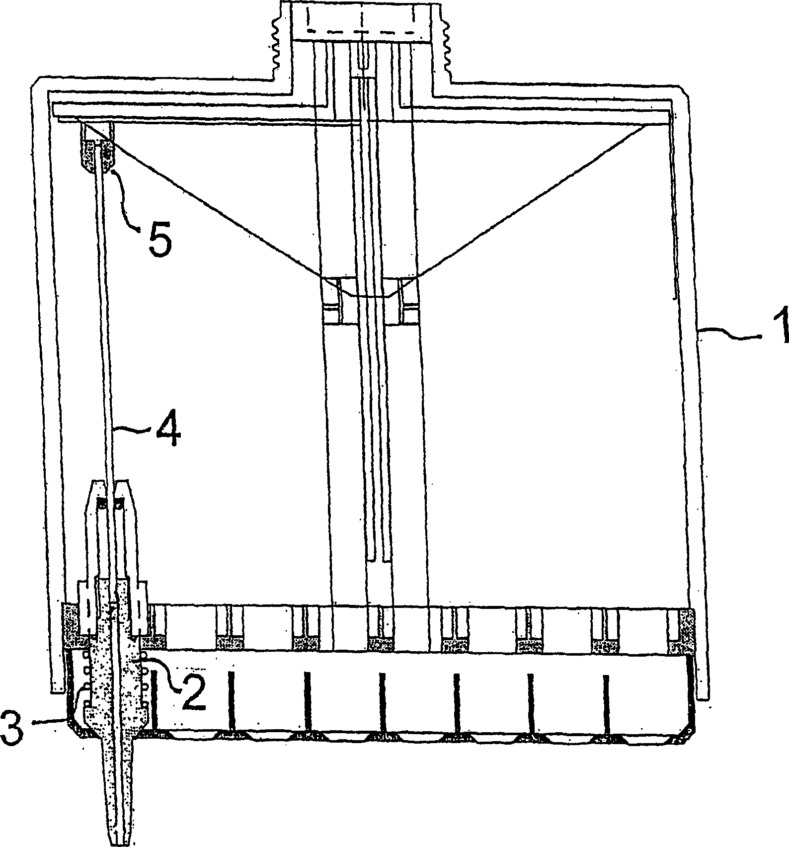
[0015] Only one of 8 identical parallel mechanisms (channels) housed in the common body 1 is shown. The suction tube and the syringe are parts of the same assembly 2 which is arranged to be movable in the pipette body 1 such that in the rest state the compression spring 3 keeps the suction tube in its outermost position. A piston 4 is movable in the barrel 2, the upper end of which is attached to the common operating mechanism 5 of the channel. The device generally includes a tip removal mechanism, the structure of which will be familiar to those skilled in the art from several prior art publications.

[0016] When picking up the prongs 7 (not shown) from the rack, the user can adjust the picking action so that each suction tube is retractable due to the spring 3 when the prongs are attached to the suction tubes. In this way, there is a high probability that each tine will attach with the same force, despite small angular differences between different tines and suction tubes....


PUM


Abstract

A multichannel pipette, the suction tube arrangement of which is arranged to be resilient, so that a disposable tip is attached similarly to each suction tube regardless of the shape and elastic characteristics of a tip rack. The pipette comprises a body and a plunger-cylinder system with suction tubes for each channel. Each suction tube is thus adapted to the body, that the suction tube is movable between two extreme positions in its vertical direction with respect to the body.

Description

technical field [0001] The present invention relates to the construction of inhalation devices using disposable tips, in particular pipettes. In particular, the invention relates to the spring mechanism of the suction tube of the pipette to ensure smooth attachment of the disposable tip in the multi-channel pipette. Background technique [0002] Pipettes are commonly used in laboratory work for dispensing liquids, whereby disposable pipette tips are attached via a friction connection. The tip is a tapered plastic part proportional to the volume of liquid to be dispensed. The tip is attached to the lower end of the slightly tapered suction tube of the pipette, ie the tapered end, by inserting the tapered end into the corresponding tapered tip attachment. After use, typically by activating a mechanism, eg by the thumb, causing removal means arranged around the suction tube to move downwards, whereby the removal means pushes the tip away from the suction tube and the tip is r...

Claims


Application Information

Patent Timeline
IPC IPC(8): B01L3/02
CPCB01L3/0217B01L3/0279B01L2200/0689B01L3/02
Inventor 奥斯莫·斯沃瓦尼米珀蒂·埃克霍尔姆
Owner BIOHIT OY FI
Learn More