
Optical isolator

A technology of optical isolator and ferrule, applied in the field of optical communication, can solve the problems of increased volume of Faraday rotator, increased cost of raw materials, large installation space, etc., to achieve the effect of saving internal space, improving the scope of application, and reducing production costs

Inactive Publication Date: 2019-05-21
珠海市杰威光电科技有限公司
View PDF5 Cites 4 Cited by
  • Summary
  • Abstract
  • Description
  • Claims
  • Application Information

AI Technical Summary

Problems solved by technology

Generally, in addition to the optical parameter requirements for this kind of isolator, the product is also required to have small size, high reliability and certain economy, etc. However, some optical isolators such as figure 1 As shown, it is generally necessary to set a collimator or multiple lenses, resulting in a relatively large product volume and a large installation space; resulting in a corresponding increase in the consumed crystal material and the volume of the Faraday rotator, thereby increasing the raw material cost of the product

Method used


Image

  • Optical isolator
  • Optical isolator
  • Optical isolator

Examples


Embodiment Construction

[0028] The specific embodiments of the present invention will be further described below in conjunction with the accompanying drawings. It should be noted here that the descriptions of these embodiments are used to help understand the present invention, but are not intended to limit the present invention. In addition, the technical features involved in the various embodiments of the present invention described below may be combined with each other as long as they do not constitute a conflict with each other.

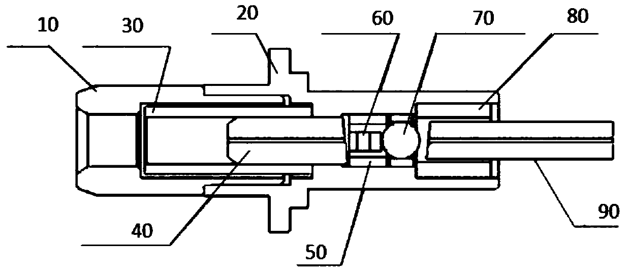
[0029] An optical isolator such as figure 2 As shown, it includes a front cover 10, a rear cover 20, a front sleeve 30, a front ferrule 40, a magnetic ring 50, a CORE assembly 60, a lens assembly 70, a rear sleeve 80 and a rear ferrule 90;

[0030] The rear cover 20 is sleeved on the end of the front cover 10, the front sleeve 30 is arranged inside the front cover 10, the front ferrule 40 is arranged inside the front sleeve 30, the inside of the front ferrule 40 is pro...


PUM


Abstract

The invention provides an optical isolator comprising a front cover, a rear cover, a front sleeve, a front ferrule, a magnetic ring, a CORE assembly, a lens assembly, a rear sleeve and a rear ferrule.On the basis of the structure, the CORE assembly and the lens assembly carry out one-way transmission on an optical signal, so that no collimator or a plurality of lenses need to be set in the optical isolator and thus the product size and production cost are reduced. Since a polarization-independent displacement type assembly or a polarization-dependent absorption type assembly is arranged inside the CORE assembly, the optical isolator is set to be a polarization-independent or polarization-dependent optical isolator, so that the application range of the optical isolator is extended. Moreover, a glass rod is used for replacing the rear sleeve and the rear ferrule, so that the internal space can be saved further and thus the product size is reduced further.

Description

technical field [0001] The invention relates to optical communication, in particular to an optical isolator. Background technique [0002] An optical isolator is a device that allows light to enter from the input end and reach the receiving end with a small loss after passing through the optical isolator; at the same time, if the light is input from the receiving end in reverse, it should generate a large loss to reach the output end, thus completing For the function of one-way isolation, common optical isolators achieve the optical isolation effect by setting the optical rotation effect of the Faraday rotator under the action of a magnetic field, and at the same time combining the anisotropy of the birefringent crystal. Generally, in addition to the optical parameter requirements for this kind of isolator, the product is also required to have small size, high reliability and certain economy, etc. However, some optical isolators such as figure 1 As shown, it is generally ne...

Claims


Application Information

Patent Timeline
IPC IPC(8): G02B6/27
Inventor 肖俊鹏
Owner 珠海市杰威光电科技有限公司
Learn More