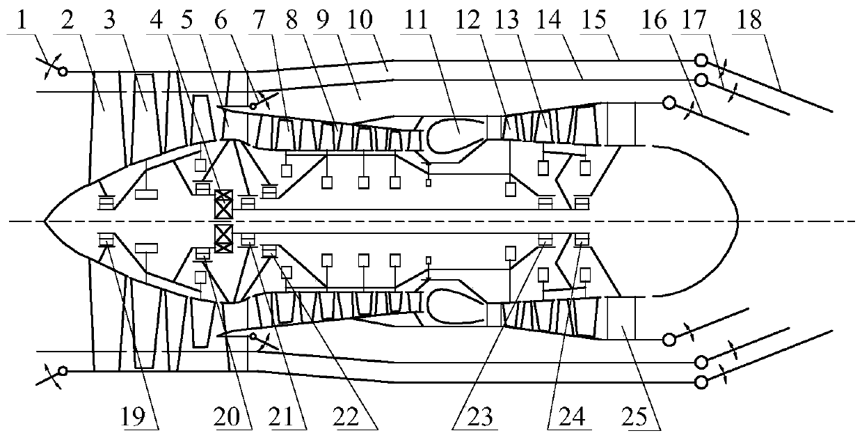
Turbofan engine with automatic bypass ratio regulating capacity
A technology of turbofan engine and adjustment ability, which is applied in the direction of engine components, machine/engine, engine lubrication, etc., can solve the problems of low propulsion efficiency, low fuel consumption rate of propulsion efficiency, high fuel consumption rate of turbojet engine, etc., to reduce Effects on weight, improved performance, improved fuel economy
- Summary
- Abstract
- Description
- Claims
- Application Information
AI Technical Summary
Problems solved by technology
Method used
Image
Examples
Embodiment approach 1
[0016] Implementation mode one: if figure 2 As shown, when the aircraft is at light load or low-speed cruise, the engine only needs to provide a small thrust that meets the basic requirements. At this time, the first valve 1 and the second valve 6 are closed, and the second culvert 9 and the third culvert Road 10 does not produce thrust, and the thrust of the engine only comes from the first duct 8. At this time, the engine transforms into a turbojet engine without connotation. In order to give full play to the advantages of the components, a The speed reducer 4 is used to reduce the blade tip tangential speed of the fan 3 without affecting the normal operation of the low-pressure turbine 13. However, since the effective working height of the fan 3 in the radial direction is reduced, the fan 3 only plays a part of the role. In addition, In order to better meet the use requirements, the third valve 16 can also be used to adjust the thrust twice in the single-duct working mode ...
Embodiment approach 2
[0017] Implementation mode two: if image 3 and Figure 4 As shown, when the aircraft needs medium thrust, the engine can close the first valve 1 or the second valve 6 according to the specific requirements of the use, open the first duct 8 and the second duct 9 double duct working mode or the first duct 8 and the third duct 10 double-duct working mode, at this time, the working mode of the first duct 8 remains unchanged, and a part of the thrust of the engine is generated, and the other part of the thrust is provided by the air entering the second duct 9 or the third duct 10 Generate; in order to better meet the use requirements, the fourth valve 17 and the fifth valve 18 are designed to further adjust the thrust of the second duct 9 and the third duct 10 respectively.
Embodiment approach 3
[0018] Implementation mode three: if Figure 5 As shown, when the aircraft needs a large thrust, the engine starts the three-duct operation mode, at this time, the first valve 1 and the second valve 6 are opened at the same time, the fan 3 is in a full working state, and the outside air enters the first duct 8 and the second duct simultaneously. The second duct 9 and the third duct 10, all three ducts generate thrust, in order to better meet the requirements, while the three ducts are working, the third valve 16, the fourth valve 17 and the fifth valve can be used 18 Make proper adjustments to the engine.
[0019] The rotor system of the engine is supported by a total of six magnetic bearings, the first bearing 19, the second bearing 20, the third bearing 21, the fourth bearing 22, the fifth bearing 23 and the sixth bearing 24. The advantage of this scheme is that it can reduce The vibration of the engine is small. At the same time, this kind of bearing also has the advantage...
PUM
 Abstract
Description
Claims
Application Information
 - R&D
- Intellectual Property
- Life Sciences
- Materials
- Tech Scout
- Unparalleled Data Quality
- Higher Quality Content
- 60% Fewer Hallucinations
Browse by: Latest US Patents, China's latest patents, Technical Efficacy Thesaurus, Application Domain, Technology Topic, Popular Technical Reports.
© 2025 PatSnap. All rights reserved.Legal|Privacy policy|Modern Slavery Act Transparency Statement|Sitemap|About US| Contact US: help@patsnap.com


