
A method for preparing an exhaust duct

A technology for exhaust ducts and molds, which is applied to manufacturing tools, ceramic molding machines, etc., can solve problems such as high noise, pitted surfaces of exhaust ducts, and delamination, so as to reduce equipment damage, increase service life, and structural strength. high effect

Active Publication Date: 2021-07-16
GUANGZHOU CAIDIE ENERGY SAVING TECH
View PDF8 Cites 0 Cited by
  • Summary
  • Abstract
  • Description
  • Claims
  • Application Information

AI Technical Summary

Problems solved by technology

[0008] The molding process of the exhaust channel in the prior art adopts the method of horizontal vibration, which can promote the flow of the slurry on the one hand and discharge the gas in the slurry on the other hand; however, the bottom area of ​​the casting cavity is located below the mold, The gas detached from the slurry will encounter the mold upwards. During the horizontal vibration process, this part of the gas is difficult to flow out to the left or right, and the gas that cannot be discharged is formed on the surface of the exhaust channel, causing the surface of the exhaust channel to Phenomena such as pores and pockmarks appear, and the smoothness is poor
[0009] In the prior art, there is an application of increasing the frequency of horizontal vibration. The main defect of this method is that high-intensity vibration is likely to cause segregation of the grout (concrete segregation), stratification, and uneven internal composition and structure of the grout; Excessive noise in the process can easily lead to deformation of the mold, which is not conducive to the long-term use of the mold;
[0010] In order to reduce the occurrence of pockmarks and other phenomena, there is also the application of increasing the water-cement ratio of the slurry to increase the fluidity of the slurry in the prior art. Since the overall thickness of the exhaust channel is relatively thin, generally about 15mm, the water-cement ratio of the slurry is improved. After the gray ratio, the strength of the exhaust duct will be insufficient, and it is difficult to meet the requirements of the vertical bearing capacity of the exhaust duct products specified in the industry standard; moreover, after increasing the water-cement ratio of the slurry, there are still obvious numbness. surface phenomenon

Method used


Image

  • A method for preparing an exhaust duct
  • A method for preparing an exhaust duct
  • A method for preparing an exhaust duct

Examples


Embodiment 1

[0070] Example 1 (Tilting Vibration Mode 1)

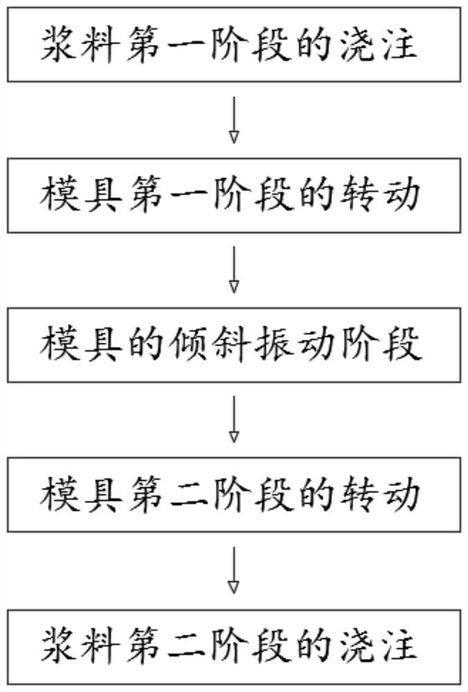
[0071] Such as figure 1 -8, a method of preparing an exhaust passage, after the mold positioning, processes:

[0072] Pouring of the first stage of the slurry:

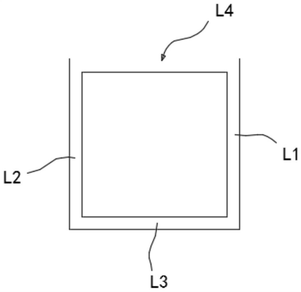
[0073] In the top region L4 of the mold, the slurry is dispersed into the first side region L1 and the second side side region L2, and aggregate in the bottom region L3, continuous pouring slurry to the slurry to fill the bottom Regional L3;

[0074] Preferably, during the casting of the first phase of the slurry, the amount of the dispersion flowing into the first side region L1 and the second side region L2 slurry is generally the same or close, and after the slurry is filled with the bottom area, the first There is a certain amount of slurry in the side area L1, and the second side side region L2.

[0075] Among them, during the casting process of the first phase of the slurry, the horizontal vibration of the mold can be performed, or the horizontal vibration of the mold m...

Embodiment 2

[0095] Example 2 (Tilting Vibration Mode 2)

[0096] Such as Figure 9 -16, a method of preparation of an exhaust tract, especially the preparation method of the mechanism exhaust trail, after the mold positioning, the process:

[0097] The rotation of the first phase of the mold:

[0098] When the mold is rotated around the first direction toward the first side region L5 to the inclined posture, at this time, a cylindrical β is formed between the bottom region L7 in the cavity.

[0099] Preferably, the size β having an inclination angle between the bottom region L7 and the horizontal plane is poured into a cavity, further, the magnitude β of 20 ° is 20 °, and the inclination size β of the present embodiment is 15 °. Compared with the tilt vibration mode of Example 1, the inclination angle in this embodiment is smaller and the vibration effect is more prominent.

[0100] Among them, after the mold is rotated to the inclinement posture, the first side portion L5 and the second side...

Embodiment 3

[0121] Example 3 (Tilting Vibration Mode 2)

[0122] A method of preparing an exhaust passage, the difference from Embodiment 2 is that the slope of the mold is also provided in the tilt of the mold:

[0123] The periodic swing process of the mold: the mold is rotated around the first direction or back to the first side area to change the size of the plane and the horizontal plane in which the bottom region in the cast cavity is placed, through multiple circulation The swing process is realized to completely discharge the gas in the bottom region (including gas in the bottom region slurry), to avoid ventilation of the vent side wall (especially the side walls of the molded cavity bottom region), etc. .


PUM


Abstract

The invention provides a method for preparing an exhaust duct. A pouring molding cavity adapted to the shape of the exhaust duct is formed in the mold. The pouring molding cavity has a top area and a bottom area arranged up and down, and two symmetrically arranged bottom areas. The first side region and the second side region of the side, wherein, during the pouring process of the slurry, the mold is rotated around the first direction to an inclined posture at least in part, so that the plane of the bottom region in the casting cavity is in the same plane as An inclination angle is formed between the horizontal planes, and the mold vibrates continuously or periodically when the mold is in an inclined posture. In the present invention, the gas in the slurry is fully exhausted by vibrating under the tilted attitude of the mold to reduce pockmarks, pores and the like in the exhaust channel.

Description

Technical field [0001] The present invention belongs to the field of residential exhaust path technology, and more particularly to a portion of the discharging process in the exhaust track, the mold is in an inclined state and performs the vibration of the mold to achieve a gas sufficiently discharged in the slurry to reduce the exhaust trail. Production method of exhaust air in the phenomenon of sequel, air hole. Background technique [0002] The exhaust tract is a widely used building component in the residential buildings, which use the exhaust gas in the kitchen and the exhaust gas in the bathroom, and the exhaust tract is prefabricated, and it is equipped to the designated location within the building. [0003] The current exhaust tract is mostly used in pure artificial production. There is a large occupancy site, and the technical proficiency of operators is highly required, and the thickness of the thickness of the ventilation wall is difficult to control. With the develop...

Claims


Application Information

Patent Timeline
Patent Type & Authority Patents(China)
IPC IPC(8): B28B1/08
Inventor 李志李惠红聂法玉谭源生
Owner GUANGZHOU CAIDIE ENERGY SAVING TECH
Learn More