
Cold heading process for connecting flange of automobile exhaust pipe

A technology for automobile exhaust and connecting flanges, which is applied in the direction of manufacturing tools, metal processing equipment, forging/pressing/hammer devices, etc., can solve the problems of high loss of machining tools, high manufacturing costs, and high material costs, and achieve improved The effect of installing dimensional accuracy, shortening processing time, and optimizing production process

Active Publication Date: 2020-06-23
无锡苏明达科技有限公司
View PDF10 Cites 0 Cited by
  • Summary
  • Abstract
  • Description
  • Claims
  • Application Information

AI Technical Summary

Problems solved by technology

The former is assembled because the gap between the flange aperture and the bolt outer diameter is about 1mm, which may easily cause deviations in the assembly surface of the opposing flange, affecting the sealing effect and the appearance quality of product assembly; the latter is connected by welding, which requires more professionalism in the welding operation process. High, and it is easy to cause false welding and missing welding at the welding part, causing the welding bolt to fall off; after welding, the bolt installation position is heated and deformed, and the deformation is uncontrollable. The subsequent shaping process must be followed to achieve the installation dimensional accuracy, but the shaping process may cause the welding part to be desoldered , this variable is uncontrollable, which causes problems in customer assembly
[0003] Moreover, the HRB hardness of 400 series stainless steel is about 100, the loss of machining tools is too high, the material utilization rate of bar processing is kept at 25-30%, the material utilization rate is low, the material cost is too high, and the manufacturing cost is too high

Method used


Image

  • Cold heading process for connecting flange of automobile exhaust pipe
  • Cold heading process for connecting flange of automobile exhaust pipe
  • Cold heading process for connecting flange of automobile exhaust pipe

Examples


Embodiment 1

[0039] Such as Figure 1-8 As shown, a cold heading process for connecting flanges of automobile exhaust pipes mainly includes the following steps:

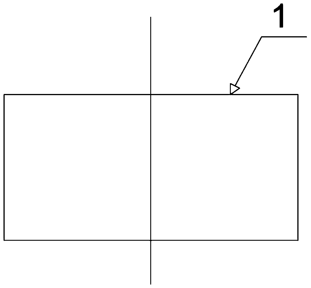
[0040] S1: Making the original bar through a cutting die to obtain a cylindrical blank 1;

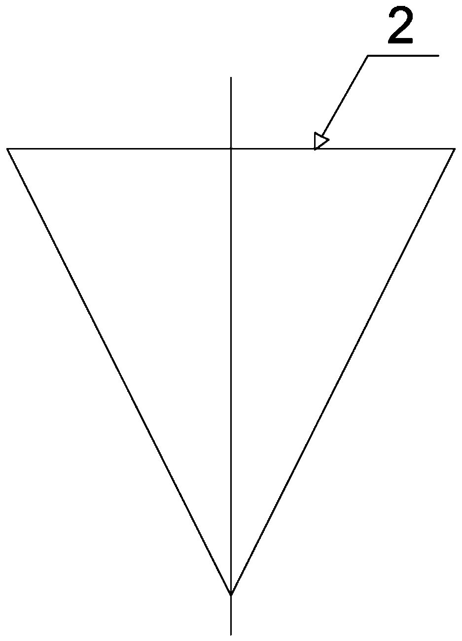
[0041] S2: Cold heading the cylindrical blank 1 into a conical shape through the first cold heading die, leaving a machining allowance of 0.5-1 mm to obtain the first semi-finished blank 2;

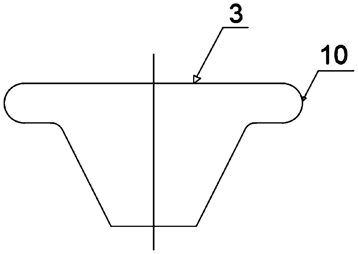
[0042] S3: cold heading the first semi-finished blank 2 into a rounded truncated shape through the second cold heading die, and extruding the upper end out of the preformed flange 10 to obtain the second semi-finished blank 3;

[0043] S4: Extrude chamfering at both ends of the second semi-finished blank 3 through the third cold heading die, and extrude the upper positioning groove 8 and the lower positioning groove 9 at the upper and lower ends thereof, so as to obtain the third semi-finished blank 4;

[0044] S5: extruding the lower positioning gr...

Embodiment 2

[0050] Such as Figure 1-8 As shown, a cold heading process for connecting flanges of automobile exhaust pipes mainly includes the following steps:

[0051] S1: Making the original bar through a cutting die to obtain a cylindrical blank 1;

[0052] S2: Cold heading the cylindrical blank 1 into a conical shape through the first cold heading die, leaving a machining allowance of 0.5-1 mm to obtain the first semi-finished blank 2;

[0053] S3: cold heading the first semi-finished blank 2 into a rounded truncated shape through the second cold heading die, and extruding the upper end out of the preformed flange 10 to obtain the second semi-finished blank 3;

[0054] S4: Extrude chamfering at both ends of the second semi-finished blank 3 through the third cold heading die, and extrude the upper positioning groove 8 and the lower positioning groove 9 at the upper and lower ends thereof, so as to obtain the third semi-finished blank 4;

[0055] S5: extruding the lower positioning gr...

Embodiment 3

[0061] Such as Figure 1-8 As shown, a cold heading process for connecting flanges of automobile exhaust pipes mainly includes the following steps:

[0062] S1: Making the original bar through a cutting die to obtain a cylindrical blank 1;

[0063] S2: Cold heading the cylindrical blank 1 into a conical shape through the first cold heading die, leaving a machining allowance of 0.5-1 mm to obtain the first semi-finished blank 2;

[0064] S3: cold heading the first semi-finished blank 2 into a rounded truncated shape through the second cold heading die, and extruding the upper end out of the preformed flange 10 to obtain the second semi-finished blank 3;

[0065] S4: Extrude chamfering at both ends of the second semi-finished blank 3 through the third cold heading die, and extrude the upper positioning groove 8 and the lower positioning groove 9 at the upper and lower ends thereof, so as to obtain the third semi-finished blank 4;

[0066] S5: extruding the lower positioning gr...


PUM


Abstract

The invention discloses a cold upsetting process for an automobile exhaust pipe connecting flange. The cold upsetting process mainly comprises the following steps of sequentially performing cold upsetting with a cutting die, a first cold upsetting die, a second cold upsetting die, a third cold upsetting die, a fourth cold upsetting die, a fifth cold upsetting die and a sixth cold upsetting die toobtain an initial connecting flange blank, then cleaning and soaking the initial connecting flange blank with a flange washing solution, and drying the initial connecting flange blank in a preheatingfurnace at a temperature of 260-280 DEG C; then moving the dried initial connecting flange blank into an annealing furnace, and performing heat preservation for 4-6h at 790-850 DEG C, wherein applyinga high-energy pulse current for 2min to the connecting flange blank every 45s; and cooling the connecting flange blank to 480 DEG C at a speed of 110-130 DEG C, then cooling the connecting flange blank to a room temperature by adopting a hydrogen spraying cooling manner, and then performing turning to obtain a finished connecting flange product. The cold upsetting process effectively improves theproduction efficiency of the connecting flange, increases the utilization rate of steel and lowers the manufacturing cost.

Description

technical field [0001] The invention relates to the technical field of mechanical processing, in particular to a cold heading process for connecting flanges of automobile exhaust pipes. Background technique [0002] The existing 400-series stainless steel is widely used in automobile exhaust systems due to its good high temperature resistance and corrosion resistance. Since the connection parts of the automobile exhaust system must be arranged in accordance with the overall arrangement of the engine powertrain, the shape and size of the connecting flanges are relatively different. many. If the flange assembly is assembled through free installation of bolts or after welding of bolts and flanges. The former is assembled because the gap between the flange aperture and the bolt outer diameter is about 1mm, which may easily cause deviations in the assembly surface of the opposing flange, affecting the sealing effect and the appearance quality of product assembly; the latter is c...

Claims


Application Information

Patent Timeline
Patent Type & Authority Patents(China)
IPC IPC(8): B21K1/76B21J5/08B21J5/10B21J13/02
Inventor 程健钮学新
Owner 无锡苏明达科技有限公司
Learn More