A miniature encapsulated ionization gauge

An ionization gauge and encapsulation technology, which is applied in the field of micro-encapsulation ionization gauges, can solve the problems of the inability to extend the measurement lower limit of micro-ionization gauges, limit the characteristics of micro-packages, and electron bombardment to eliminate the high-temperature hot cathode effect and prolong the trajectory. length, to overcome the effect of low sensitivity

Active Publication Date: 2021-05-28
LANZHOU INST OF PHYSICS CHINESE ACADEMY OF SPACE TECH
View PDF8 Cites 0 Cited by
  • Summary
  • Abstract
  • Description
  • Claims
  • Application Information

AI Technical Summary

Problems solved by technology

[0006] However, for miniature ionization gauges, the traditional hot filament is not conducive to reducing the gas output and power consumption. However, there is a common problem of low sensitivity, which makes the lower limit of measurement of such miniature ionization gauges impossible to extend
[0007] In Mook Choi et al. proposed a miniature three-pole carbon nanotube cathode ionization gauge, such as figure 1 As shown, the cathode 14 of the ionization gauge is arranged on the cathode base 13. At about 200V, electron field emission is realized, and electrons move to the anode grid 15 under the action of the electric field. This method overcomes the high temperature outgassing effect, and the vacuum degree The lower limit of measurement reached 10 -5 Pa level, however, if the lower limit of measurement needs to be further extended, neither increasing the emission current nor increasing the size of the gauge proposed by the inventor In Mook Choi et al. is not the optimal choice, because increasing the emission current will cause larger electron bombardment outgassing , while increasing the gauge size limits its tiny package features

Method used


Image

  • A miniature encapsulated ionization gauge
  • A miniature encapsulated ionization gauge
  • A miniature encapsulated ionization gauge

Examples


Embodiment Construction

[0027] The present invention will be described in detail below with reference to the accompanying drawings and examples.

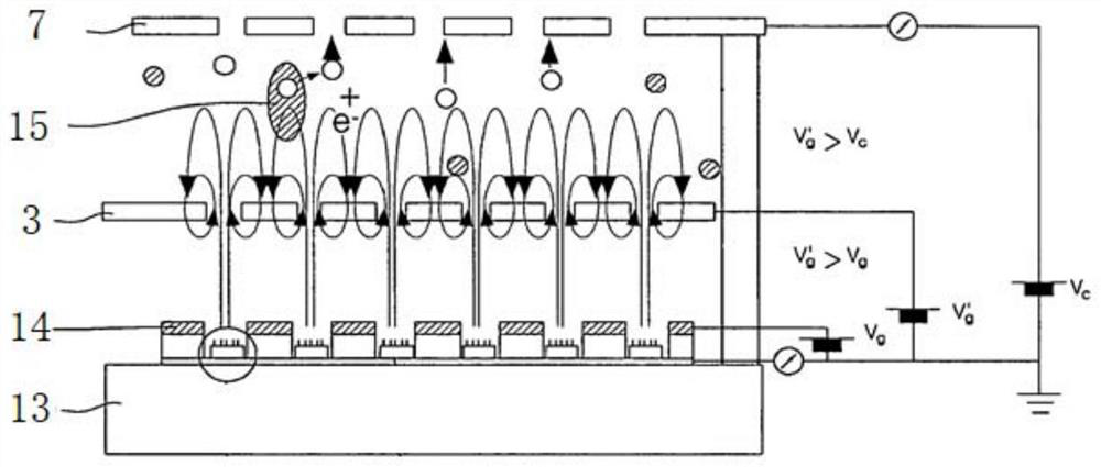
[0028] According to the working principle of the ionization gauge, improving the sensitivity is a practical and feasible technical way to extend this kind of miniature package ionization gauge. Therefore, according to the theoretical calculation formula of the sensitivity S, it can be known that

[0029]

[0030] Among them, σ represents the ionization cross section, k is the Boltzmann constant, T is the Kelvin temperature, and L is the length of the trajectory of electrons in the ionization region. Therefore, extending L is an effective technical approach to improve the sensitivity of the miniature ionization gauge.

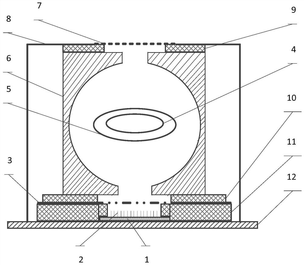
[0031] This embodiment provides a kind of miniaturized encapsulation type ionization gauge, such as figure 2 As shown, the ionization gauge includes a carbon nanotube cathode substrate 1, a carbon nanotube array 2, a gate electrode 3, a...


PUM

PropertyMeasurementUnit
diameteraaaaaaaaaa

Abstract

The invention provides a miniature packaged ionization gauge, comprising a field emission cathode, a gate, an anode assembly, a collector, and a packaging shell; the field emission cathode is arranged at the bottom of the packaging shell, and the field emission cathode, gate, and anode assembly The collector is coaxially arranged, and the electrodes are insulated; the collector has a grid structure, which is fixedly connected to the top of the package shell, and is used to receive ion flow, and at the same time conduct with the vacuum environment to introduce gas molecules; the gate is a field emission cathode Provide the extraction electric field, after the field emitted electrons enter the anode assembly, a local saddle-shaped electric field is formed in the anode assembly, the field emission electrons reciprocate in the anode assembly and ionize the gas molecules, and the ion flow generated after ionization is received by the collector. The invention can overcome the high-temperature hot cathode effect, simultaneously improve the sensitivity and extend the lower limit of measurement.

Description

technical field [0001] The invention relates to the technical field of vacuum measurement, in particular to a miniature packaged ionization gauge. Background technique [0002] With the rapid development of science and technology, high-tech fields have put forward higher requirements for ultra-high vacuum measurement, especially in the fields of advanced semiconductor manufacturing, space science, surface science, etc., for low outgassing, no thermal effect, low power consumption and miniaturization High vacuum measurement technology puts forward more urgent requirements. [0003] Traditional ionization gauges include three basic components: cathode, anode and ion collector. The working principle of the ionization gauge is that the electrons are emitted from the cathode and ionize the gas molecules during the reciprocating movement of the anode area, and the gas phase ion flow I generated by the ionization c Received and detected by the collector, the electrons moving back...

Claims


Application Information

Patent Timeline
Patent Type & Authority Patents(China)
IPC IPC(8): H01J41/06G01L21/34
Inventor 张虎忠成永军孙健郭美如赵澜陈联陈会颖
Owner LANZHOU INST OF PHYSICS CHINESE ACADEMY OF SPACE TECH
Why Eureka
Try Eureka