


Quick Research
Generate reliable direction feasibility study reports for your R&D in just a few steps.

Technical Q&A
Discover and master advanced knowledge NOW. Basics, ideas, possibilities, all at once.

Find Solutions
As an expert in R&D theories, this can generate solutions to your technical problems instantly.

Evaluate Feasibility
Analyze your overall solution with one click, know your potential R&D risks in advance.

Monitor Landscape
Get weekly tech updates, stay abreast of the latest tech innovations and key insights.
Unpowered rolling beating sweeping device and method
A cleaning device and power technology, used in cleaning devices, transportation and packaging, conveyor objects, etc., can solve the problems of inability to remove powdery materials, frequent deviations of equipment, etc., to avoid dust and material scattering, and even knocking force. Rhythmic, energy-reducing effect
- Summary
- Abstract
- Description
- Claims
- Application Information
AI Technical Summary
Problems solved by technology
Method used
Image

Examples
Embodiment 1
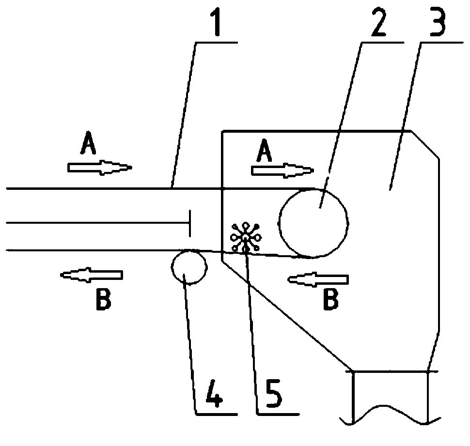
[0037] Such as Figure 1 to Figure 3 As shown, a kind of unpowered rolling cleaning device of the present embodiment comprises belt surface 1, head driving drum 2, head funnel 3, unpowered rolling cleaning device 5 and bracket 13, and described belt surface 1 is close to The head driving drum 2 rotates, and the head funnel 3 is installed outside the head driving drum 2 and the unpowered rolling cleaner 5. The distance between the inner side of the head funnel and the outer contour of the rolling cleaner is ≥ 30 mm. In this embodiment, the head The distance between the inner side of the funnel and the outer contour of the rolling cleaner is 30mm, and the head funnel 3 can make the materials conveyed by the belt and the materials knocked down by the unpowered rolling cleaner 5 concentrate and fall, avoiding dust and material scattering; the unpowered The rolling cleaner 5 is arranged on the inner surface of the belt surface 1 in the return direction, and by beating the opposite ...
Embodiment 2
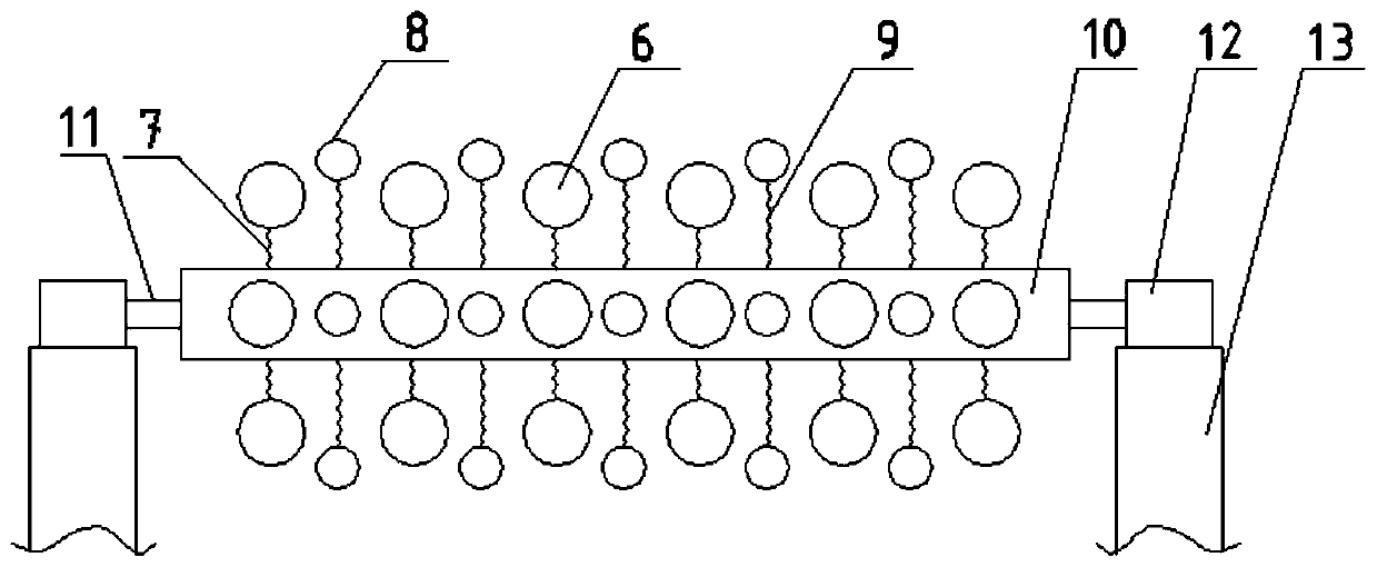
[0039] Such as Figure 1 to Figure 3 As shown, this embodiment is basically the same as Embodiment 1. Further, one end of the hammer head I6 is connected to the spring I7 to form a beating mechanism, and one end of the hammer head II8 to the spring II9 is connected to form a rotating mechanism. The spring I7 and the spring The other end of II9 is all vertically fixed on the rolling bearing 10, and the said rotating mechanism and the beating mechanism are arranged crosswise on the rolling bearing 10.
[0040] In this embodiment, the cleaning mechanism of one static and one dynamic is formed by cross arrangement. After the rotating mechanism rotates, the beating mechanism immediately pats and knocks the belt, and cooperates with each other to make the materials fall rhythmically.
Embodiment 3
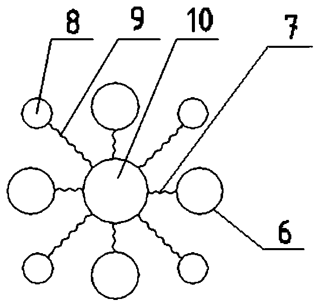
[0042] Such as Figure 1 to Figure 3 As shown, this embodiment is basically the same as any embodiment of embodiment 1 or embodiment 2. Further, the diameter of the hammer head I6 is larger than that of the hammer head II8, and the length of the spring I7 is shorter than that of the spring II9.
[0043] In this embodiment, the larger hammer head I cooperates with the shorter spring I to form a greater beating force, which can promptly remove the powdery material adhering to the belt.
PUM
| Property | Measurement | Unit |
|---|---|---|
| Diameter | aaaaa | aaaaa |
| Length | aaaaa | aaaaa |
| Diameter | aaaaa | aaaaa |
Abstract
Description
Claims
Application Information
 - R&D Engineer
- R&D Manager
- IP Professional
- Industry Leading Data Capabilities
- Powerful AI technology
- Patent DNA Extraction
Browse by: Latest US Patents, China's latest patents, Technical Efficacy Thesaurus, Application Domain, Technology Topic, Popular Technical Reports.
© 2024 PatSnap. All rights reserved.Legal|Privacy policy|Modern Slavery Act Transparency Statement|Sitemap|About US| Contact US: help@patsnap.com