
Multifunctional tool head shifting mechanism

A tool head and multi-functional technology, applied in the field of multi-function tool head switching mechanism, can solve the problems of inability to realize flexible conversion of multiple tool heads, complex processing technology, small adjustment angle, etc., and achieve easy and smooth advancement, The effect of flexible conversion and improved efficiency

Inactive Publication Date: 2019-05-17
NANTONG TIANMAO MACHINERY MFG CO LTD
View PDF15 Cites 0 Cited by
  • Summary
  • Abstract
  • Description
  • Claims
  • Application Information

AI Technical Summary

Problems solved by technology

[0008] (1) The crowbar in the above structure is adjusted by the cooperation between the ratchet and the pawl. Due to the characteristics of its own structure, when the ratchet and the pawl are locked, it is still prone to one-way wrong rotation of the ratchet. Therefore, it is very troublesome to adjust to the original angle again before use; in addition, the adjustment can only be adjusted within a range of nearly 180 degrees, and the adjustment angle is relatively small;
[0009] (2) In this structure, very high requirements are put forward for the ratchet hole of the pry head, the coaxiality between the ratchet and the rotating shaft, and the cooperation between the ratchet and the pawl, and between the pawl and the elastic locking ball. complex;
[0010] (3) In this structure, there is only one conversion tool head, which cannot realize flexible conversion between multiple tool heads, and the use efficiency is low

Method used


Image

  • Multifunctional tool head shifting mechanism
  • Multifunctional tool head shifting mechanism
  • Multifunctional tool head shifting mechanism

Examples


Embodiment 1

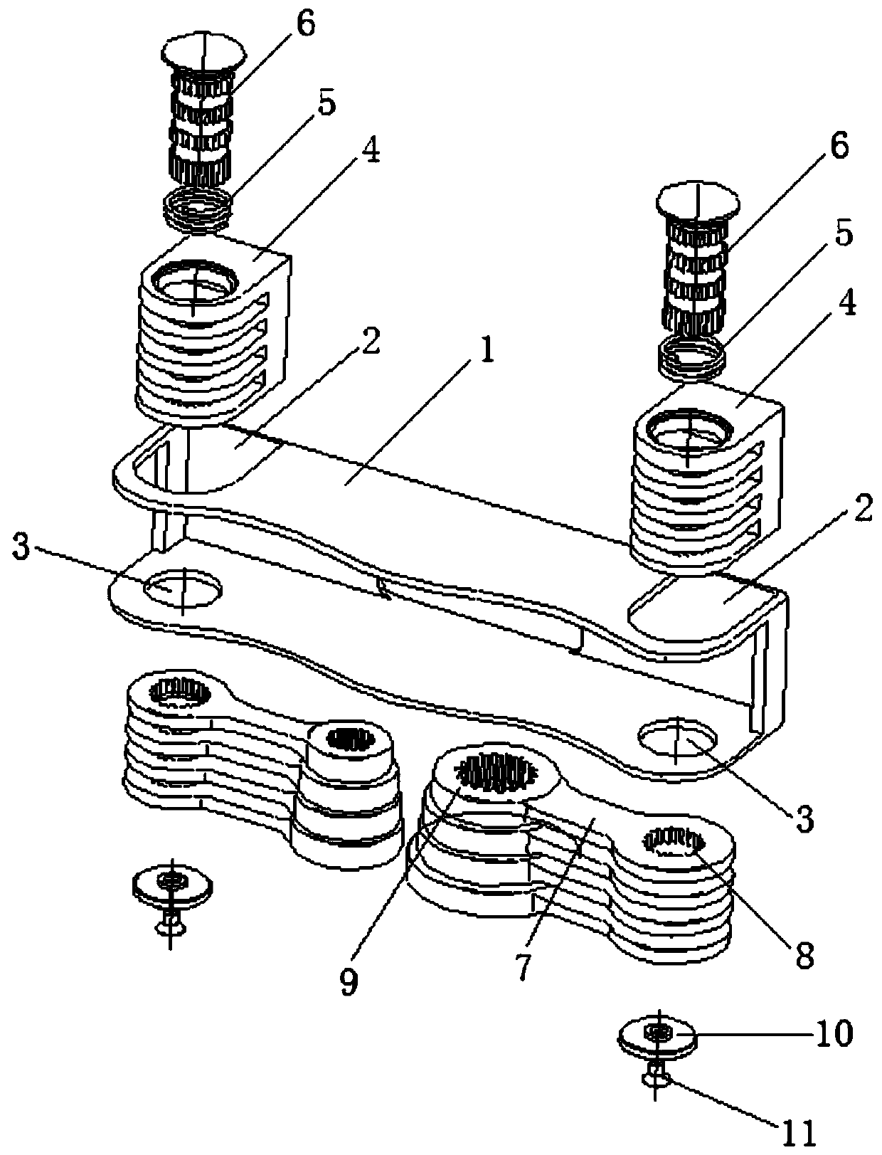
[0045] Such as figure 1 , figure 2 , Figure 6 to Figure 10 A multifunctional tool head switching mechanism shown includes:

[0046] Mounting bracket 1, said mounting bracket 1 includes a pair of symmetrically arranged side plates and bottom plates, wherein the two ends of one side plate are respectively provided with first through holes 2 for accommodating U-shaped support 4, and the other side plate The two ends of each are respectively provided with second through holes 3 for accommodating the caps 10 to be installed.

[0047] In this embodiment, the shape of the first through hole 2 is consistent with the shape of the U-shaped support 4 , and the shape of the second through hole 3 is consistent with the shape of the cap 10 .

[0048] U-shaped support 4, the U-shaped support 4 is successively provided with a third through hole 42 coaxially arranged to place a return spring, three smooth fourth through holes 43 and a splined hole at the end. The fifth through hole 45, t...

Embodiment 2

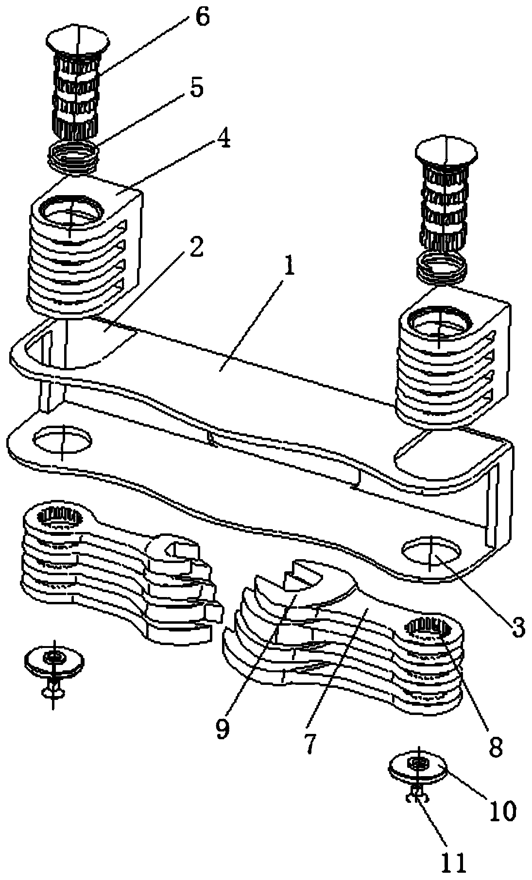
[0054] Such as image 3 , Figure 4 , Figure 6 to Figure 10 A multifunctional tool head switching mechanism shown includes:

[0055] Mounting bracket 1, said mounting bracket 1 includes a pair of symmetrically arranged side plates and bottom plates, wherein the two ends of one side plate are respectively provided with first through holes 2 for accommodating U-shaped support 4, and the other side plate The two ends of each are respectively provided with second through holes 3 for accommodating the caps 10 to be installed.

[0056] In this embodiment, the shape of the first through hole 2 is consistent with the shape of the U-shaped support 4 , and the shape of the second through hole 3 is consistent with the shape of the cap 10 .

[0057] U-shaped support 4, the U-shaped support 4 is successively provided with a third through hole 42 coaxially arranged to place a return spring, three smooth fourth through holes 43 and a splined hole at the end. The fifth through hole 45, t...


PUM


Abstract

The invention discloses a multifunctional tool head shifting mechanism. The multifunctional tool head shifting mechanism comprises a mounting support, U-shaped supports, pin shafts, reset springs, tool head mechanisms, caps and screws, wherein the mounting support comprises a pair of side plates and a bottom plate, the side plates are arranged symmetrically, the two ends of one side plate are respectively provided with first through holes for accommodating the U-shaped supports, and the two ends of the other side plate are respectively provided with second through holes for accommodating the cover caps; a third through hole for containing one reset spring, at least one inner smooth fourth through hole and a fifth through hole with an inner spline hole in the end part are formed in each U-shaped support in sequence, and gaps for accommodating the rotating ends of the tool head mechanisms to penetrate through is arranged between every two adjacent holes; the pin shafts are provided witha plurality of outer spline sections which are coaxially arranged and integrally machined and formed, optical axis sections and limiting knob sections; and the number of the tool head mechanisms is multiple. The multifunctional tool head shifting mechanism can integrate various types of tools, and is flexible, not prone to blocking and long in service life.

Description

technical field [0001] The invention relates to a tool structure, in particular to a multifunctional tool head switching mechanism. Background technique [0002] With the development of modern machinery and metallurgical technology, hand tools are constantly updated and developed in terms of shape design and material use, fully considering design factors such as mechanics and human body functions; with the development of social economy and the fine division of labor in industrial production, The manufacture of hand tools is more specialized and their functions more diverse. [0003] As is well known, some hand tools are equipped with a structure capable of adjusting and locking the tool head and the handle relative to each other. [0004] For example, Chinese Patent Application No. 200820027739.1 discloses a rotary nail remover or crowbar, including a pry head and a pry bar, which is characterized in that the pry head and the pry bar are hinged, and the pry head and the pry...

Claims


Application Information

Patent Timeline
Patent Type & Authority Applications(China)
IPC IPC(8): B25B13/56B25F1/04
Inventor 蒋步斌
Owner NANTONG TIANMAO MACHINERY MFG CO LTD
Learn More