Alloy machining drill bit

A drill bit and alloy technology, applied in metal processing equipment, metal processing machinery parts, drill repairing, etc., can solve the problems of debris clogging, unsatisfactory, affecting work efficiency, etc., to reduce surface wear, reduce friction, and reduce damage Effect

Active Publication Date: 2019-05-17
LUCKY GOLDJYX CO LTD
View PDF6 Cites 2 Cited by
  • Summary
  • Abstract
  • Description
  • Claims
  • Application Information

AI Technical Summary

Problems solved by technology

[0004] The purpose of the present invention is to provide a kind of processing drill bit for alloy, to solve the problem that the length of the drill bit is fixedly installed during the work of the existing drill bit, the length of the drill bit cannot be adjusted according to the needs, and the needs during use cannot be met. If the debris is not cleaned in time during work, it will cause debris blockage and affect work efficiency. The existing drill bit cannot be cleaned of debris during work, which cannot meet the technical problems of use.

Method used


Image

  • Alloy machining drill bit
  • Alloy machining drill bit
  • Alloy machining drill bit

Examples


Embodiment Construction

[0033] The technical solutions of the present invention will be clearly and completely described below in conjunction with the embodiments. Apparently, the described embodiments are only some of the embodiments of the present invention, not all of them. Based on the embodiments of the present invention, all other embodiments obtained by persons of ordinary skill in the art without creative efforts fall within the protection scope of the present invention.

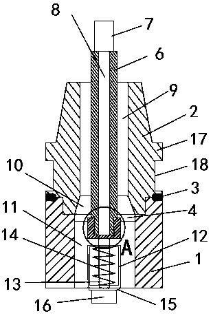
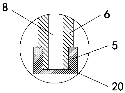
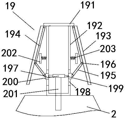
[0034] See Figure 1-5 , a processing drill for alloys, comprising a lower working shaft 1, an upper working shaft 2, a mounting table 5, a first sleeve 6, a drill bit 7, an anti-clogging mechanism 19 and a blade 22, wherein the upper working shaft 2 is embedded and installed in the lower The top of the working shaft 1, and the upper working shaft 2 and the lower working shaft 1 are circular structures, and a sealing ring 3 is arranged between the upper working shaft 2 and the lower working shaft 1, and the sealing ring 3 c...


PUM


Abstract

The invention discloses an alloy machining drill bit. A lower work shaft, an upper work shaft, an installing table, a first sleeve, a drill bit body, an anti-blockage mechanism and a blade are included. The upper work shaft is embedded and installed in the top end of the lower work shaft through a bolt, an installing plate is horizontally arranged in the top end of the lower work shaft through a bolt, the middle of the lower surface of the installing plate is inwards concaved to form a square groove, and a circular through hole is formed in the middle of the square groove. The installing tableis arranged in the square groove and internally provided with the first sleeve. The top end of the first sleeve penetrates through the through hole formed in the square groove of the installing plateand extends towards an inner cavity of the upper work shaft. The first sleeve penetrates through the upper work shaft and extends upwards. The drill bit body is arranged at the top end of the first sleeve and fixedly connected with a connecting shaft through a positioning pin, wherein the connecting shaft is arranged in the first sleeve; and through pushing, a second connecting rod can be pushedto move up and down in the vertical direction, accordingly, two sliding blocks can be pushed to move, and finally the included angle between a first side wing plate and the vertical direction can be adjusted.

Description

technical field [0001] The invention relates to a processing drill bit, in particular to a processing drill bit for an alloy, and belongs to the technical field of processing drill bits. Background technique [0002] The drill bit is the main component of drilling equipment, and its main function is to break the rock and form a wellbore. The rotary drill bit is a drill bit commonly used in the petroleum industry at present. Driven by machinery, the rotary drill bit will rotate, thereby driving the entire drill bit to produce a centripetal movement, and through cutting and grinding, the rock will be cracked and broken, and it will play a role in drilling down. effect. The drill bit is one of the main drilling equipment. According to the different working environment and regional environment, the specification and shape of the drill bit should also be different. When carrying out oil drilling work, it should be based on specific needs and specific design schemes. [0003] Th...

Claims


Application Information

Patent Timeline
Patent Type & Authority Applications(China)
IPC IPC(8): B23B51/00B23B47/22B23Q11/00
Inventor 严远峰黄乾
Owner LUCKY GOLDJYX CO LTD
Why Eureka
Try Eureka