A unilateral three-dimensional manipulator for forging
What is Al technical title?
Al technical title is built by PatSnap Al team. It summarizes the technical point description of the patent document.
A manipulator and forging technology, applied in the field of manipulators, can solve the problems of inability to rotate horizontally, inconvenient installation, and the support strength of the unilateral three-dimensional manipulator needs to be improved, so as to achieve the effect of reasonable design and enhanced support strength.
Active Publication Date: 2020-09-08
CHINA FORGING MACHINERY
View PDF7 Cites 0 Cited by
Summary
Abstract
Description
Claims
Application Information
AI Technical Summary
This helps you quickly interpret patents by identifying the three key elements:
Problems solved by technology
Method used
Benefits of technology
Problems solved by technology
[0003] The unilateral three-dimensional manipulator used for forging has the problem that it can only clamp and fix the forging and cannot rotate horizontally on the basis of clamping and fixing the forging, so that it is impossible to carry out multiple identical forging structures on the same forging surface. If it is reached, it is necessary to add a corresponding forging structure on the mold, and the installation is inconvenient. At the same time, the support strength of the unilateral three-dimensional manipulator needs to be improved.
Method used
Image
Click on the blue label to locate the original text in one second.
Reading with bidirectional positioning of images and text.
Examples
Embodiment Construction
[0020] The following will clearly and completely describe the technical solutions in the embodiments of the present invention with reference to the accompanying drawings in the embodiments of the present invention. Obviously, the described embodiments are only some, not all, embodiments of the present invention. Based on the embodiments of the present invention, all other embodiments obtained by persons of ordinary skill in the art without making creative efforts belong to the protection scope of the present invention.
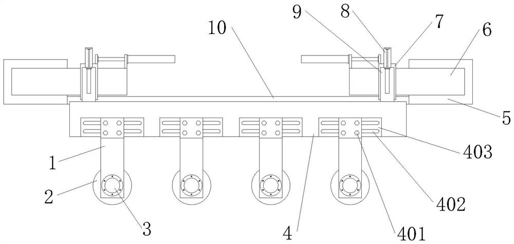
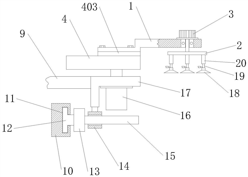
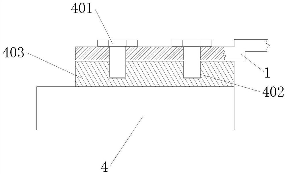
[0021] see Figure 1-3 As shown, a forging unilateral three-dimensional manipulator includes a bearing square rod 5, a transverse guide rail 6, a longitudinal guide rail 8, a U-shaped slide plate 7, a strip slide plate 9, an adsorption rotation mechanism and a guide support mechanism, and the bearing square rod 5 are provided with two, and the two bearing square bars 5 are installed vertically on the ground, and the top end faces of the two bearing square bars...
PUM
Abstract
The invention belongs to the technical field of manipulators, in particular to a forging single-sided three-dimensional manipulator. The forging single-sided three-dimensional manipulator comprises acarrier strip plate, a circular steel plate, a micro stepping motor, a lifting strip plate, a bearing square bar, a transverse guide rail, a U-shaped sliding plate, a longitudinal guide rail, a strip-shaped slide plate, a fixed square plate, a T-shaped chute, a T-shaped sliding block, a strip-shaped square block, a slip ring, a round bar, a pneumatic push rod, an L-shaped long plate, a suction disk, a thin cylinder and a round pipe. The forging single-sided three-dimensional manipulator is reasonable in design, special forging side surfaces and the top surface of a forging part are adjusted tothe forging position, forging same structures multiple times in one same forging area is facilitated, the supporting strength of sucking and holding a fixed structure of the forging part is enhanced,and the forging part is stably moved to the next forging position; and the corresponding micro stepping motor is started to run to drive the circular steel plate and the forging part fixed at the bottom of the circular steel plate through the suction disk to rotate, the appropriate angle is rotated, and the to-be-forged surface is located at the forging position.
Description
technical field [0001] The invention belongs to the technical field of manipulators, in particular to a forging single-sided three-dimensional manipulator. Background technique [0002] Forging is the collective name of forging and stamping. It is a forming process that uses the hammer, anvil, punch or through the die of the forging machine to exert pressure on the blank to cause plastic deformation to obtain the required shape and size of the workpiece. . [0003] The unilateral three-dimensional manipulator used for forging has the problem that it can only clamp and fix the forging and cannot rotate horizontally on the basis of clamping and fixing the forging, so that it is impossible to carry out multiple identical forging structures on the same forging surface. If it is reached, it is necessary to add a corresponding forging structure on the mold, and the installation is inconvenient. At the same time, the support strength of the unilateral three-dimensional manipulator...
Claims
Application Information
Patent Timeline
Application Date:The date an application was filed.
Publication Date:The date a patent or application was officially published.
First Publication Date:The earliest publication date of a patent with the same application number.
Issue Date:Publication date of the patent grant document.
PCT Entry Date:The Entry date of PCT National Phase.
Estimated Expiry Date:The statutory expiry date of a patent right according to the Patent Law, and it is the longest term of protection that the patent right can achieve without the termination of the patent right due to other reasons(Term extension factor has been taken into account ).
Invalid Date:Actual expiry date is based on effective date or publication date of legal transaction data of invalid patent.