SXM2GPU-simulated test alarm device
A simulation device and alarm device technology, which is applied in the field of GPU testing, can solve problems such as unfavorable conditions, damage to boards such as motherboards and GPUs, reduce costs, etc., and achieve the effect of in-position signal optimization and improved anti-interference ability
- Summary
- Abstract
- Description
- Claims
- Application Information
AI Technical Summary
Problems solved by technology
Method used
Image
Examples
Embodiment 1
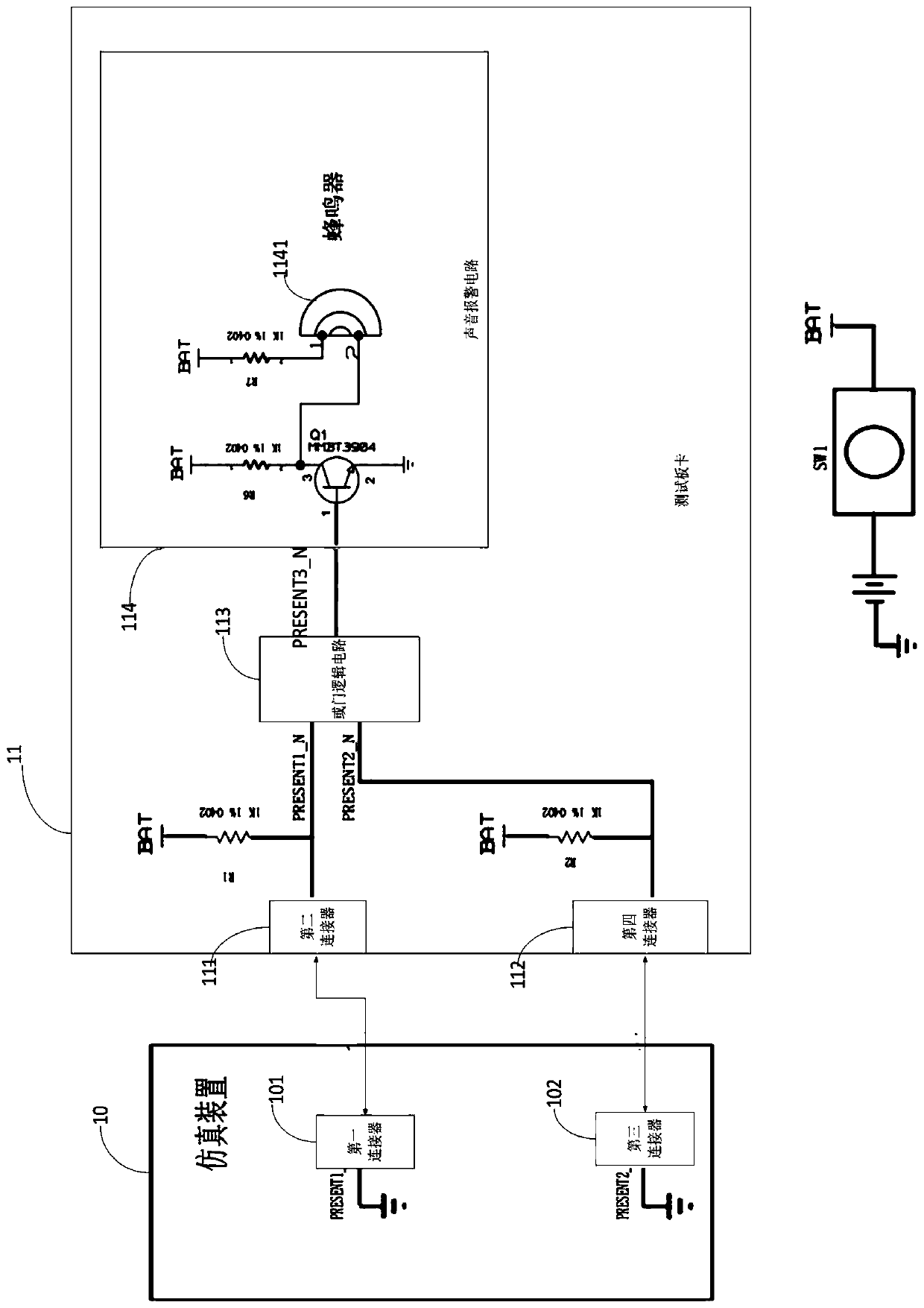
[0027] Such as figure 1 As shown, a test alarm device for simulating SXM2GPU includes: a simulation device 10 and a test board 11, the simulation device 10 is placed in the card slot of the SXM2GPU, and the test board 11 communicates with the first connector group and the second connector group. The simulation device 10 is connected, wherein the first connector group includes a first connector 101 and a second connector 111, the second connector group includes a third connector 102 and a fourth connector 112, and the simulation device 10 includes a first a connector 101 and a third connector 102;
[0028] The test board 11 includes: a second connector 111, a fourth connector 112, an OR gate logic circuit 113 and a sound alarm circuit 114, the test board is connected with the simulation device 10 through the second connector 111 and the fourth connector 112, One of the first in-position signal sending ends of the second connector 111 is connected to the first input end of the ...
Embodiment 2
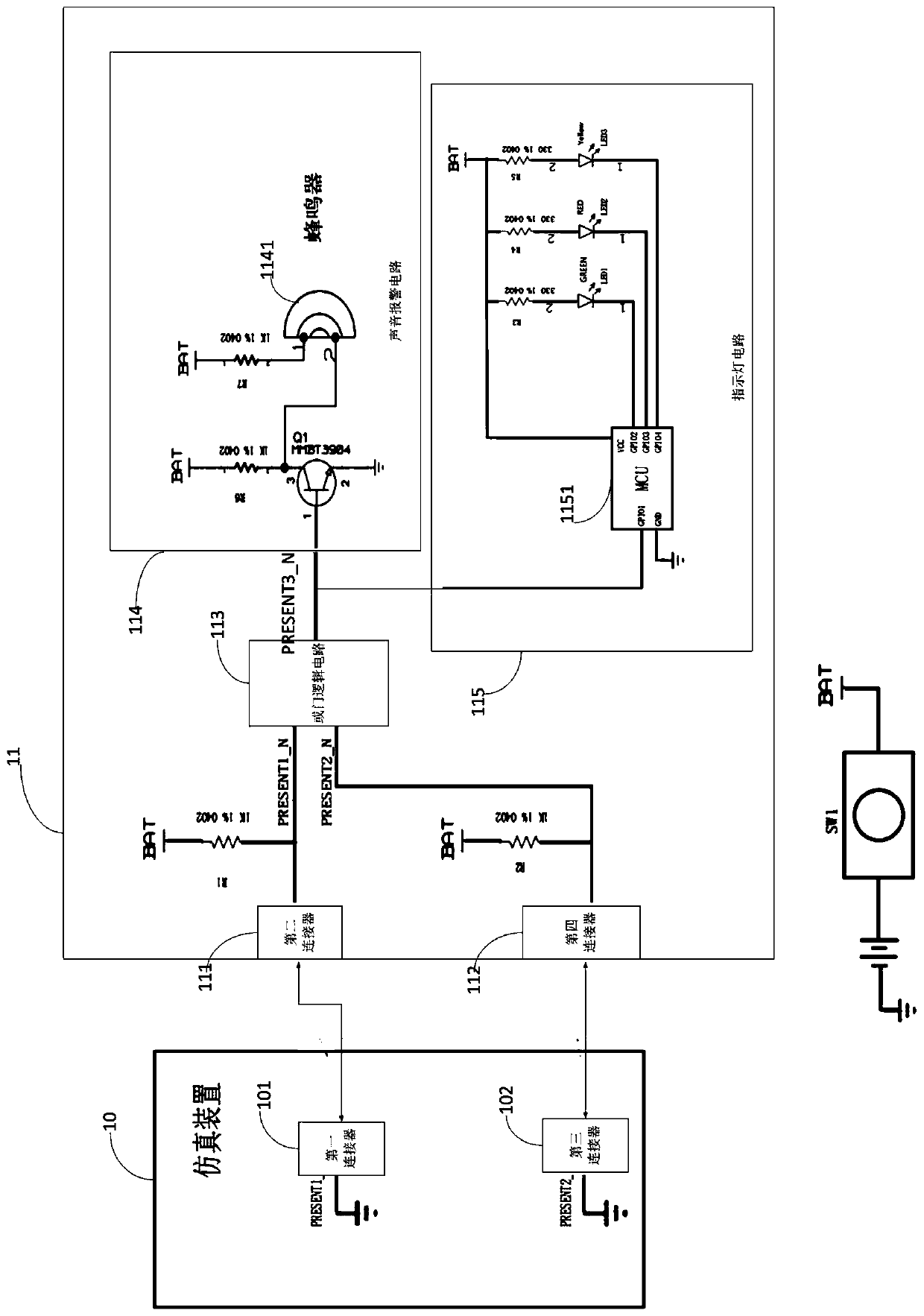
[0033] Such as figure 2 As shown, the difference from Embodiment 1 of the technical solution of the present invention is that the test board 11 further includes an indicator light circuit 115 , and the input end of the indicator light circuit 115 is connected to the output end of the OR gate logic circuit 113 . Indicator lamp circuit 115 comprises microprocessor 1151, light-emitting diode LED1, light-emitting diode LED2, light-emitting diode LED3, resistance R3, resistance R4, resistance R5, the power supply terminal VCC of microprocessor 1151 is connected with one end of switch SW1, the other end of switch SW1 One end is connected to the positive pole of the battery BAT, and the negative pole of the battery BAT is grounded; the ground terminal of the microprocessor 1151 is grounded; the general input / output interface GPIO1 of the microprocessor 1151 is connected to the output end of the OR gate logic circuit 113; The input / output interface GPIO2 is connected to the cathode o...
Embodiment 3
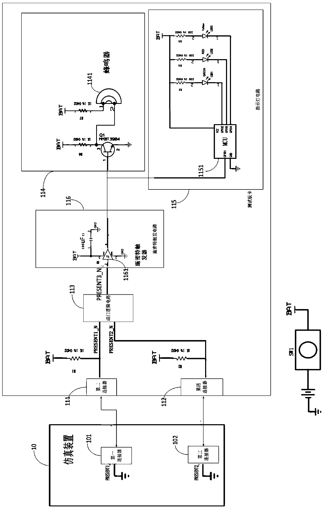
[0036] Such as image 3 As shown, different from Embodiment 1 or Embodiment 2 of the technical solution of the present invention, the test board 11 also includes a Schmitt trigger circuit 116, and the input end of the Schmitt trigger circuit 116 is connected to the output end of the OR gate logic circuit 113 , the output end of the Schmitt trigger circuit 116 is connected to the input end of the sound alarm circuit 114 or the indicator light circuit 115 .
[0037] The Schmitt trigger circuit 116 includes a Schmitt trigger 1161 and a capacitor C1. The input terminal of the Schmitt trigger 1161 is connected to the output terminal of the OR gate logic circuit 113; the power supply terminal VCC of the Schmitt trigger 1161 is connected to the capacitor C1 all the way. The other end is connected to one end of the switch SW1, the other end of the switch SW1 is connected to the positive pole of the battery BAT, and the negative pole of the battery BAT is grounded; the ground terminal ...
PUM
 Abstract
Description
Claims
Application Information
 - R&D
- Intellectual Property
- Life Sciences
- Materials
- Tech Scout
- Unparalleled Data Quality
- Higher Quality Content
- 60% Fewer Hallucinations
Browse by: Latest US Patents, China's latest patents, Technical Efficacy Thesaurus, Application Domain, Technology Topic, Popular Technical Reports.
© 2025 PatSnap. All rights reserved.Legal|Privacy policy|Modern Slavery Act Transparency Statement|Sitemap|About US| Contact US: help@patsnap.com


