Bituminous coal Oya dilatometer automatic striking device
A technology of automatic lifting device and dilatometer, applied in measurement devices, instruments, scientific instruments, etc., can solve the problems of experimental data influence, cumbersome operation, data error, etc., and achieve simple operation, high degree of automation and reduce data error. Effect
- Summary
- Abstract
- Description
- Claims
- Application Information
AI Technical Summary
Problems solved by technology
Method used
Image
Examples
Embodiment 1
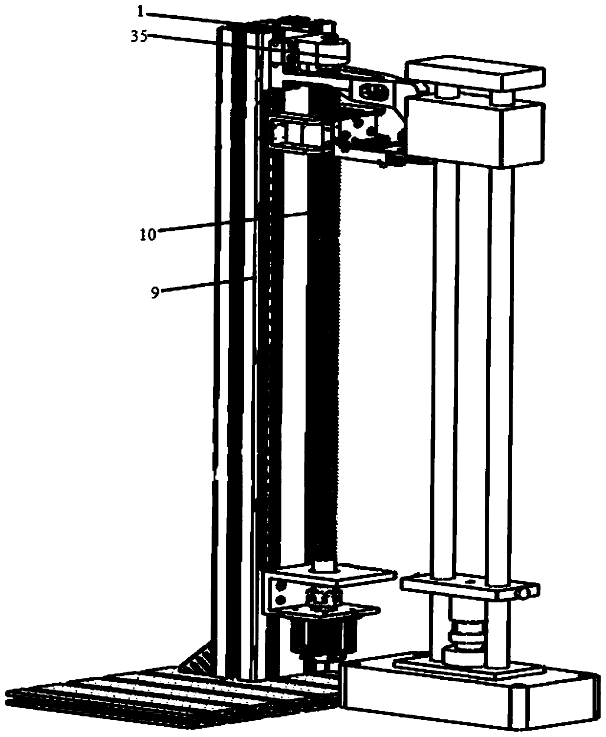
[0026] Such as figure 1 as shown, figure 1 It is a structural diagram of the automatic striking device of the bituminous coal Aurora dilatometer of the present invention; the automatic striking device of the bituminous coal Aurya dilatometer of the present invention includes a forming striker 21, a fixed bottom plate 20, a right angle piece 19, an automatic lifting device and an automatic replacement strike pole device.
[0027] The forming striker 21, the automatic lifting device and the automatic replacement of the striking rod device are all fixedly arranged on the fixed base plate 20, and the forming striking device 21, the automatic lifting device, the automatic replacement of the striking rod device and the described The right-angled parts 19 are arranged between the fixed bottom plates 20, and the right-angled parts 19 are used to reinforce the connection state between the forming striker 21, the automatic lifting device and the automatic replacement of the striking ro...
Embodiment 2
[0034] like figure 2 , image 3 , Figure 4 as shown, figure 2 It is a structural schematic diagram of the automatic lifting device; image 3 It is a schematic diagram of the connection structure of the lifting and fixing platform; Figure 4 It is a schematic diagram of the connection structure of the first driving device; the lifting support platform 16 is placed horizontally, and the side is fixed on the lifting frame 9 by T-shaped bolts, and the lower end of the lifting screw 10 is installed on the The upper plane of the lifting support table 16 is connected to the first driving device 18 through the lifting coupling 17; the upper end of the lifting screw 10 is mounted on the screw bearing through a tapered roller bearing On the seat 1, the screw bearing seat 1 is fixed on the upper end of the lifting frame 9 by T-shaped bolts.
[0035] The first driving device 18 is placed vertically and fixed on the lower plane of the lifting support platform 16 by screws, so that ...
Embodiment 3
[0044] like Figure 5 and Image 6 as shown, Figure 5 It is a structural schematic diagram of the device for automatically changing the striking rod; Image 6 It is a schematic diagram of the connection structure of the replacement fixed platform; the replacement support platform 14 is placed horizontally, and the side is fixed on the replacement frame 31 by T-shaped bolts, and the lower end of the replacement screw rod 11 is installed on the replacement frame 31 through a tapered roller bearing. The replacement support table 14 is on the upper plane, and is connected with the second driving device 22 through the second coupling 15, and the upper end of the replacement screw 11 is installed on the screw fixing seat 30 through a tapered roller bearing. Above, the screw fixing seat 30 is fixed on the upper end of the replacement frame 31 by T-shaped bolts.
[0045] The second driving device 22 is vertically installed on the lower plane of the replacement support table 14 thr...
PUM
 Abstract
Description
Claims
Application Information
 - Generate Ideas
- Intellectual Property
- Life Sciences
- Materials
- Tech Scout
- Unparalleled Data Quality
- Higher Quality Content
- 60% Fewer Hallucinations
Browse by: Latest US Patents, China's latest patents, Technical Efficacy Thesaurus, Application Domain, Technology Topic, Popular Technical Reports.
© 2025 PatSnap. All rights reserved.Legal|Privacy policy|Modern Slavery Act Transparency Statement|Sitemap|About US| Contact US: help@patsnap.com


