High-power resilience dual drive resilience circulating water pump unit

A circulating water pump, dual-drive technology, applied in the direction of machine/engine, pump, pump device, etc., can solve the problems of limitation, slip, inability to automatically overrun the clutch or the direct-connected operation of the pneumatic tire clutch, etc., to reduce the conveying energy consumption, The effect of reducing energy consumption

Pending Publication Date: 2019-05-07
唐山瓦特合同能源管理有限公司
View PDF3 Cites 2 Cited by
  • Summary
  • Abstract
  • Description
  • Claims
  • Application Information

AI Technical Summary

Problems solved by technology

[0007] Under such design conditions, on the one hand, the rated operating speed of the energy-efficient hydraulic turbine unit is usually lower than the operating speed of the water pump, and most of them have slip, so they cannot be directly connected through an automatic overrunning clutch or a pneumatic tire clutch.
On the other hand, if such a huge amount of residual pressure energy is still transferred to "a dual-drive energy-regenerating circulating water pump unit (patent number: 201520427949. : 201520427950.2) "on the input shaft of the water pump, the working torque of the above-mentioned one-way diaphragm overrunning clutch reaches more than 14300Nm when transmitting 900kw shaft power, and the working torque will reach more than 25000Nm when transmitting 16000kw shaft power, and the torque far exceeds 8000-10000Nm The upper limit of the applicable range of the nominal torque of the universal overrunning clutch, so the function of the overrunning clutch also limits the closed-loop recovery and recycling of the residual pressure energy of the high-power circulating water delivery pump set and the parallel operation steam turbine driving the circulating water pump backwater

Method used


Image

  • High-power resilience dual drive resilience circulating water pump unit

Examples


Embodiment Construction

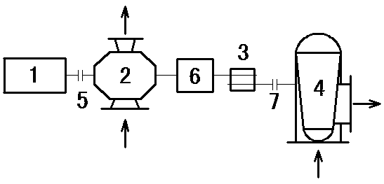
[0022] The present invention is described in detail below in conjunction with embodiment and accompanying drawing.

[0023] see figure 1 , a high-power energy-regenerating double-drive energy-regenerating circulating water pump unit, the circulating water pump 2 adopts a single-stage double-suction double-shaft extension mid-opening water pump, the motor 1 adopts a high-voltage rare earth permanent magnet synchronous motor, and the hydraulic turbine unit 4 is a mixed-flow type Water turbine unit; the motor 1 is connected to one end of the circulating water pump 2 through the first diaphragm coupling 5, the other end of the circulating water pump 2 is connected to the output shaft of the gearbox 3 through the pneumatic tire clutch 6, and the input shaft of the gearbox 3 passes through the first The two-diaphragm coupling 7 is connected with the output shaft of the hydraulic turbine unit 4 .

[0024] The gearbox 3 is a speed-up gearbox with the input shaft and the output shaft ...


PUM


Abstract

The invention relates to a high-power resilience dual drive resilience circulating water pump unit. The high-power resilience dual drive resilience circulating water pump unit comprises a motor, a circulating water pump and a hydraulic turbine machine unit, and the motor and the hydraulic turbine machine unit are arranged at the two ends of the circulating water pump in a coaxial system mode. A pneumatic tube clutch and a gearbox are further included, the motor is connected with one end of the circulating water pump through a first diaphragm coupling, the other end of the circulating water pump is connected with an output shaft of the gearbox through the pneumatic tube clutch, and an input shaft of the gearbox is connected with an output shaft of the hydraulic turbine machine unit througha second diaphragm coupling. According to the high-power resilience dual drive resilience circulating water pump unit, own output circulating water backwater excess pressure energy of the high-power circulating water pump unit can be safely recycled, backwater excess pressure energy of a turbine drive circulating water pump unit operated parallelly can be further recycled simultaneously, resilience power limitation subjected due to rotating speed and one-way exceeding coupling normal torque limit of an original dual drive resilience circulating water pump unit is overcome, and total backwaterexcess pressure energy closed-loop recycling and circulating utilization of a circulating water conveying system when the turbine drive circulating pump operates can be met.

Description

technical field [0001] The invention relates to a process energy recovery device in the field of industrial circulating water delivery systems, in particular to a high-power energy recovery double-drive energy recovery circulating water pump unit. Background technique [0002] The high-power circulating water delivery pump set is the key equipment for circulating water supply of large and medium-sized circulating water fields in modern coal chemical and petrochemical enterprises, and it is also the main energy-consuming equipment for coal chemical and petrochemical enterprises. In order to improve energy utilization efficiency and recover the heat of surplus or by-product steam of chemical process equipment, many newly built large and medium-sized circulating water stations and existing circulating water stations have undergone technical transformation, and are usually equipped with a large number of steam turbines to drive high-power circulating water pumps. Replace part of...

Claims


Application Information

Patent Timeline
Patent Type & Authority Applications(China)
IPC IPC(8): F04D13/04F04D13/06
Inventor 李正荣乔豫川卓春友李有生张承斌文开革
Owner 唐山瓦特合同能源管理有限公司
Why Eureka
Try Eureka