
Parking device for new energy automobile

A new energy vehicle and parking device technology, applied in the field of new energy vehicle parking devices, can solve the problems of no parking protection function, safety accidents, etc., and achieve the effect of strong practicability and high safety performance

Pending Publication Date: 2019-05-03
JINGCHU UNIV OF TECH
View PDF5 Cites 2 Cited by
  • Summary
  • Abstract
  • Description
  • Claims
  • Application Information

AI Technical Summary

Problems solved by technology

[0003] Chinese patent application publication number is that CN109235957A discloses a kind of multifunctional new energy automobile parking device, and this device has two parking spaces, can be used not only in personal home, also can be used in places such as shopping mall, hospital, school with dense crowd, but The device does not have a parking protection function, and a driver with poor technology is prone to safety accidents when parking

Method used


Image

  • Parking device for new energy automobile
  • Parking device for new energy automobile
  • Parking device for new energy automobile

Examples


Embodiment 1

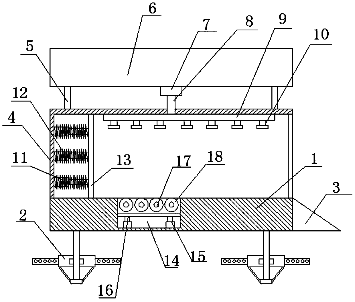
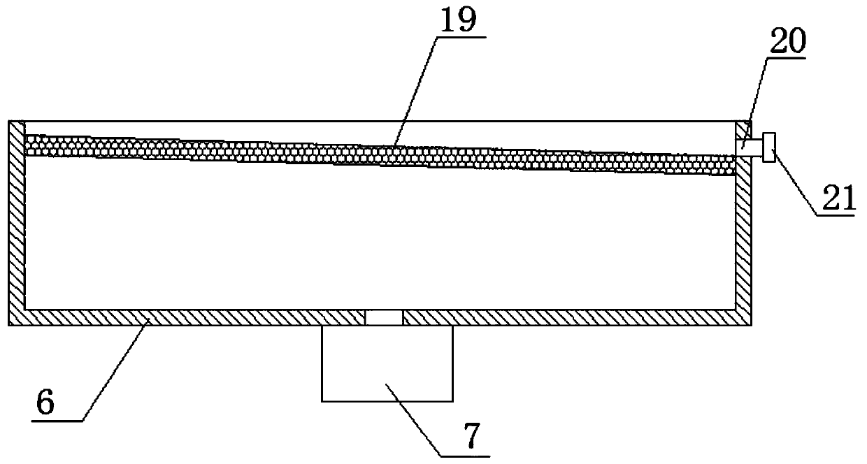
[0023] refer to figure 1 and figure 2 , in an embodiment of the present invention, a parking device for new energy vehicles, comprising a base 1, the four corners of the lower side of the base 1 are provided with a fixing assembly 2, the right end of the base 1 is provided with a triangular-shaped vehicle entry seat 3, and the base 1 The upper side is provided with a protective cover 4, the upper end of the protective cover 4 is provided with several pillars 5, the upper end of the pillar is provided with a rain cover 6, and the lower end of the rain collection cover 6 is provided with a water pump 7, and the water pump 7 A water delivery pipe 8 is arranged on the top, and the lower end of the water delivery pipe 8 is connected with a spray pipe 9 arranged in the protective cover 4. The spray pipe 9 is provided with a number of shower heads 10. The setting of this structure can be used for The rainwater is collected and filtered, and the vehicle is cleaned by using the rainw...

Embodiment 2

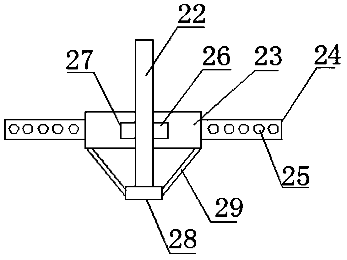
[0027] refer to image 3 , on the basis of Embodiment 1, the fixing assembly 2 includes a fixing rod 22, the upper end of the fixing rod 22 is connected to the base 1, and the outer side of the fixing rod 22 is provided with a fixing seat 23, and the fixing seat 23 The outer side is provided with some buried pipes 24, the buried pipes 24 are provided with some buried holes 25, the inside of the fixed base 23 is provided with a number of limiting grooves 27, and the outer side of the fixed rod 22 is provided with a number of spacer and spacer The slot 27 fits the limit block 26 , and the lower end of the fixed rod 22 is provided with a supporting plate 28 , and the supporting plate 28 is connected to the fixing seat 23 through a connecting piece 29 . The structure of the device is set. When in use, the fixing assembly 2 is buried underground, which can improve the stability of the connection between the device and the ground and improve the safety of use.


PUM


Abstract

The invention relates to the technical field of parking devices, in particular to a parking device for a new energy automobile. The parking device for the new energy automobile comprises a base. Fixing assemblies are arranged at the four corners of the lower side of the base, a plurality of telescopic rods are arranged at the left end in a protective cover, buffering springs are arranged outside the telescopic rods, a buffering plate is arranged at the right ends of the telescopic rods, a groove is formed in the upper side, close to the buffering plate, of the base, a plurality of rotating shafts arranged vertically are arranged in the groove, rollers are arranged on the rotating shaft, a plurality of electronic telescopic rods are arranged at the lower end in the groove, and a braking plate is arranged at the upper ends of the electronic telescopic rods. According to structural arrangement of the parking device for the new energy automobile, under the action of the buffering springs and the rollers, the action of parking protection can be achieved, safety is high, and practicability is high.

Description

technical field [0001] The invention relates to the technical field of parking devices, in particular to a parking device for new energy vehicles. Background technique [0002] Electric vehicles have no exhaust gas produced by internal combustion engine vehicles, and do not produce exhaust pollution. They are very beneficial to environmental protection and air cleanliness, and are almost "zero pollution". As we all know, pollutants such as CO, HC, NOX, particles, and odor in the exhaust gas of internal combustion engine vehicles form acid rain, acid mist and photochemical smog. Electric vehicles have no noise generated by internal combustion engines, and the noise of electric motors is also smaller than that of internal combustion engines. Noise is also harmful to human hearing, nerves, cardiovascular, digestion, endocrine, and immune systems. [0003] Chinese patent application publication number is that CN109235957A discloses a kind of multifunctional new energy automobi...

Claims


Application Information

Patent Timeline
Patent Type & Authority Applications(China)
IPC IPC(8): E04H6/02E04H6/42
Inventor 孙歆钰谢娅娅胡佳慧党凯文
Owner JINGCHU UNIV OF TECH
Learn More