


Quick Research
Generate reliable direction feasibility study reports for your R&D in just a few steps.

Technical Q&A
Discover and master advanced knowledge NOW. Basics, ideas, possibilities, all at once.

Find Solutions
As an expert in R&D theories, this can generate solutions to your technical problems instantly.

Evaluate Feasibility
Analyze your overall solution with one click, know your potential R&D risks in advance.

Monitor Landscape
Get weekly tech updates, stay abreast of the latest tech innovations and key insights.
Steel plate groove cutting method based on visual recognition
A bevel cutting and visual recognition technology, applied in the field of numerical control, can solve problems such as lack of machining accuracy and inability to meet workpiece machining requirements, and achieve the effects of high machining accuracy, good machining accuracy, and improved production flexibility
- Summary
- Abstract
- Description
- Claims
- Application Information
AI Technical Summary
Problems solved by technology
Method used
Image


Examples
Embodiment 1
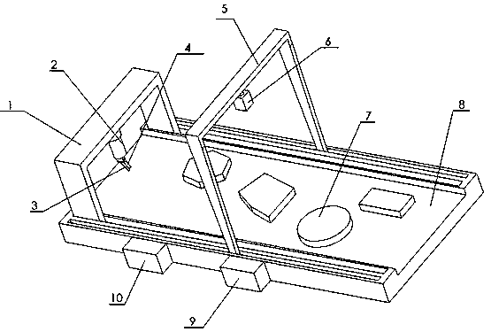
[0027] As a preferred embodiment of the present invention, with reference to the attached figure 1 , this example discloses:
[0028] The steel plate bevel cutting method based on visual recognition, including a working conveying platform 8 for conveying a workpiece 7, a first visual device 6, a first visual support 5, a cutting torch movement execution device 2, a numerically controlled cutting machine controller 10, and an image processor 9 , the cutting torch support 1 and the second visual device 4, the first visual device 6 is erected above the work conveying platform 8 through the first visual support 5, the first visual device 6 collects the image information of the workpiece 7 conveyed by the working conveying platform 8, The cutting torch motion executing device 2 is erected above the working conveying platform 8 through the cutting torch support 1, and is located behind the first vision device 6. The cutting torch motion executing device 2 is connected with the CNC c...
Embodiment 2
[0032] As another preferred embodiment of the present invention, with reference to the attached figure 1 , this example discloses:
[0033] A steel plate bevel cutting method based on visual recognition includes a visual device, a bracket, an image processor 9, and a numerically controlled cutting machine controller 10. The visual device includes a visual identification device (ie, the first visual device 6 ) and an online visual tracking device (ie, the second visual device 4 ). The support includes a CNC cutting machine torch support 1 and a visual recognition device support (namely the first visual support 5), and the CNC cutting machine torch support 1 can reciprocate along the workbench. The image processing algorithm in the image processor 9 mainly includes the contour detection and fitting algorithm of the workpiece 7 and the image edge detection and tracking algorithm.
[0034] A steel plate bevel cutting method based on visual recognition, the method comprising the ...
Embodiment 3
[0039] As another preferred embodiment of the present invention, with reference to the attached figure 1 , this example discloses:
[0040] The steel plate bevel cutting method based on visual recognition is characterized in that it includes a working conveying platform 8 for conveying workpieces 7, a first visual device 6, a first visual support 5, a cutting torch movement execution device 2, a numerically controlled cutting machine controller 10, Image processor 9, cutting torch support 1 and second visual device 4, described first visual device 6 is erected above the working conveying platform 8 by the first visual support 5, the first visual device 6 collects the workpiece that working conveying platform 8 conveys 7 image information, the cutting torch motion execution device 2 is erected above the working delivery platform 8 through the cutting torch support 1, and is located behind the first vision device 6, the cutting torch motion execution device 2 is connected with t...
PUM
 Abstract
Description
Claims
Application Information
 - R&D Engineer
- R&D Manager
- IP Professional
- Industry Leading Data Capabilities
- Powerful AI technology
- Patent DNA Extraction
Browse by: Latest US Patents, China's latest patents, Technical Efficacy Thesaurus, Application Domain, Technology Topic, Popular Technical Reports.
© 2024 PatSnap. All rights reserved.Legal|Privacy policy|Modern Slavery Act Transparency Statement|Sitemap|About US| Contact US: help@patsnap.com