Non-resonant piezoelectric generator with gyromagnetic excitation function

A non-resonance, generator technology, applied in the direction of generator/motor, piezoelectric effect/electrostrictive or magnetostrictive motor, electrical components, etc., can solve the problem of low frequency modulation ability, low power generation efficiency, difficult to control accurately, etc. problem, to achieve the effect of small mass, increase the resonance frequency, and increase the frequency bandwidth

Active Publication Date: 2019-04-26
ZHEJIANG NORMAL UNIVERSITY
View PDF6 Cites 3 Cited by
  • Summary
  • Abstract
  • Description
  • Claims
  • Application Information

AI Technical Summary

Problems solved by technology

Although the gyromagnetic excitation solves the problem of impact and noise to a large extent, it still cannot avoid the problem of low power generation efficiency caused by the mismatch between the excitation frequency and the natural frequency of the generator under different working environments
In order to adapt to the working environment under different excitation frequencies, the concept of adjustable frequency is proposed. For example, Chinese patents 201210592977.8 and 201310211521.7 respectively conduct frequency modulation by electronic control and introducing nonlinear force, but the frequency modulation ability of the former is low, while the latter is due to the nonlinearity of magnetic force. Therefore, it is not easy to control accurately; in addition, both of them use the cantilever beam piezoelectric vibrator as the power generation unit, so it is easy to be damaged during the work process, and the safety is poor

Method used


Image

  • Non-resonant piezoelectric generator with gyromagnetic excitation function
  • Non-resonant piezoelectric generator with gyromagnetic excitation function
  • Non-resonant piezoelectric generator with gyromagnetic excitation function

Examples


Embodiment Construction

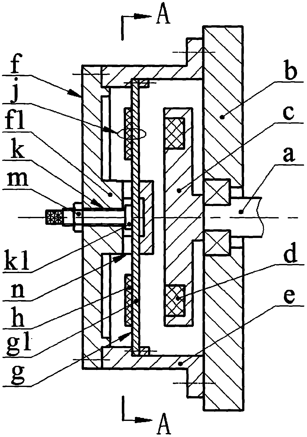
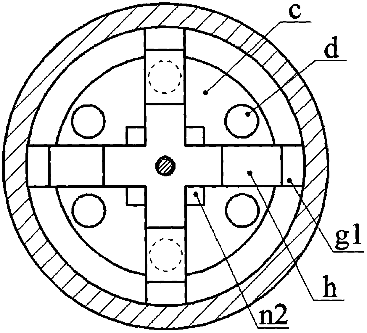
[0013] The rotating shaft a is installed on the bottom shell b through a bearing, and a turntable c is installed at the end, and the end surface of the turntable c is evenly inlaid with exciting magnets d; the left end of the shell e is installed with a top cover f through screws, and the flange end at the right end It is installed on the bottom case b through screws; the radial ferromagnetic substrate g extends from the center to have a plurality of spokes g1, the material of the ferromagnetic substrate g is nickel alloy, and the free ends of the spokes g1 are installed on the shell through screws and pressure blocks On the body e; each spoke g1 is bonded with a piezoelectric chip h, and the composite layer formed by the spoke g1 and the piezoelectric chip h constitutes a piezoelectric vibrator j; the top cover f is provided with a boss f1, and the center of the boss f1 is set There are threaded holes; the adjusting bolt k extends from the right side to the left side of the to...


PUM


Abstract

The invention relates to a non-resonant piezoelectric generator with a gyromagnetic excitation function, and belongs to the technical field of power generation. A rotating shaft is mounted on a bottomshell, a rotating disc is mounted at the end, and an exciting magnet is embedded on the rotating disc; a top cover is mounted at the left end of a shell, and the right end of the shell is mounted onthe bottom shell; a plurality of spokes are arranged on a ferromagnetic base plate in the mode of extending from the center to the exterior, and the free ends of the spokes are mounted on the shell; piezoelectric crystal plates are bonded onto the spokes, and a formed composite layer constitutes a piezoelectric vibrator; a boss is arranged on the top cover, and a threaded hole is formed in the center of the boss; an adjusting bolt extends out through the threaded hole and is provided with a locking nut in a screwed mode; the adjusting bolt is provided with a protruding ring and abuts against the center of the ferromagnetic base plate; a buckling-pressing block is connected with the boss; when the adjusting bolt is leftwards adjusted to the limit position, the left end face of the protruding ring abuts against the boss, and at the moment, the ferromagnetic base plate is in an original state without bearing action force of the adjusting bolt; and when the adjusting bolt is rightwards adjusted to the limit position, the right end face of the protruding ring abuts against the bottom face of a countersink of the buckling-pressing block, and at the moment, the ferromagnetic base plate isstill in elastic deformation of the ferromagnetic base plate.

Description

technical field [0001] The invention belongs to the technical field of power generation, and in particular relates to a non-resonance piezoelectric generator with gyromagnetic excitation. Background technique [0002] With the popularization of micro-power wireless sensors and distributed sensing technologies in the fields of health monitoring, aerospace and program control systems, the environmental pollution caused by chemical batteries as the main energy supply method cannot be ignored. For this reason, miniature generators that recycle energy such as vibration energy, human body motion energy, rotational kinetic energy and fluid energy in the natural environment are widely favored at home and abroad. The rotary piezoelectric generator is one of the important methods to recover the kinetic energy of the rotating body. The main ways to realize energy recovery are inertial excitation, toggle excitation, impact excitation and gyromagnetic excitation. Among them, gyromagnetic...

Claims


Application Information

Patent Timeline
Patent Type & Authority Applications(China)
IPC IPC(8): H02N2/18
CPCH02N2/186
Inventor 阚君武吕鹏李建平温建明王淑云曾平林仕杰张敏
Owner ZHEJIANG NORMAL UNIVERSITY
Why Eureka
Try Eureka